Continue to Site

Welcome to EDAboard.com

Welcome to our site! EDAboard.com is an international Electronics Discussion Forum focused on EDA software, circuits, schematics, books, theory, papers, asic, pld, 8051, DSP, Network, RF, Analog Design, PCB, Service Manuals... and a whole lot more! To participate you need to register. Registration is free. Click here to register now.

Defekt SPWM-Modul 1500W inverter

Denis1995

Newbie
Newbie level 3
Joined
Jun 4, 2024
Messages
4
Helped
0
Reputation
0
Reaction score
0
Trophy points
1
Activity points
25
Hello everyone, I have a small problem and hope to find a solution for it here. I have an inverter from Ective, the Power Inverter Pure Sinewave 12V SI15, input 12V, output 230V.

The inverter is installed in the motorhome and connected to a battery. There was apparently a short circuit, because the converter emits a sound once when I turn it on.

What happened:

The inverter was on in the motorhome and it was supplied with 230 V,
but now I forgot to turn it off before I connect the plug from the outside.
So there was a short circuit, because logically 2 times 230V cannot run.

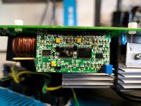
After removing the inverter, I saw that this board burned out.

Unfortunately, I couldn't find them anywhere, only comparable ones.

Could someone tell me where I would get such a new board?

Thank you in advance =)
 

Attachments

  • IMG_20240522_174825.jpg
    IMG_20240522_174825.jpg
    414.9 KB · Views: 211
Last edited by a moderator:
Did you try to reach out for Ective's customer support?
 
Have you tried to reach Ective's customer service?
Yes, I once asked if you could order the board. Unfortunately, this is not possible.

It is also not a warranty case.
 
Last edited by a moderator:
Hi,

can you provide a picture showing the part number on the large IC, as well showing the upper row of this two large ICs in more detail including traces and passive components?

BR
 
Hallo,

can you provide an image showing the part number on the large IC and also detailing the top row of these two large ICs, including traces and passive components?
Good morning

do you need more precise pictures of the complete inverter or only of the defective board?

Sorry, I'm not so good at the topic.

[Translated by moderator]
 
Last edited by a moderator:
Hi,

basically a better picture of the already provided one is needed, which shows the part numbers on the (large black) ICs (chips), as well as how they are connected to the surrounding parts.

BR
 
Hallo,

ok here are some more pictures.
 

Attachments

  • IMG_20240623_190528.jpg
    8.2 MB · Views: 146
  • IMG_20240623_190143.jpg
    8.3 MB · Views: 151
Hi,
I made a rough comparison of both external components, and it looks like both ICs are used in the same way, so at least for the resistors you should be able to determine the values. The IC should be the TF2110, a gate driver. So it should control two MOSFETs (pin #1 & #8), have a look on the other board where they are located and check if they are damaged.

It seems the IC was exposed to a too high voltage or negative negative (intrinsic low side MOSFET diode got conductive), as the COM trace (pin #2) is damaged.

Although the images are ~8MB large, it is still hard to make an "optical" inspection of the passive components around the two 16 pin ICs (TF2110).
 
images are ~8MB large,
I don´t open those large pictures... and because a preview is not available .. I can´t help
In most cases picture size of 150kBytes is sufficient.
Usually every OS provides a tool to reduce picture filesize, but there are even free to use online tools.

Klaus
 

LaTeX Commands Quick-Menu:

Similar threads

Part and Inventory Search

Welcome to EDABoard.com

Sponsor

Back
Top