Follow along with the video below to see how to install our site as a web app on your home screen.
Note: This feature may not be available in some browsers.

During the designing of a circuit how do we know where to add decoupling capacitors?How to calculate these values


100 nF is a standard value or we can select any value from 0.1uF to 0.01 uF??
- - - Updated - - -
100 nF is a standard value or we can select any value from 0.1uF to 0.01 uF? In some circuit,it uses 100nF in the input and 0.1uF at the output of the IC? So is it necessary to select only 0.1 uF at the output ?What happens when i change it to 1uF?


Decoupling capacitor values depend on the frequency of the circuit. In RF circuits you might use 100pF or less, with some larger values in parallel. For analog instrumentation I have sometimes found improvements using 100uF compared to 10uF, but that is where the circuit is working with very low frequencies.
Keith
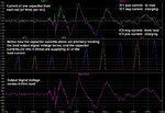
A decoupling capacitance can also be thought of as a small current supply at the point of load.
Somebody told me the above explanation. I have some doubt on this comment. I think decoupling is responsible for the filtering and in case output is not smooth, there would be small dips at the output. Due to this,is there is variation or dip in the current (I am not sure correct me if I am not)