Continue to Site

Welcome to EDAboard.com

Welcome to our site! EDAboard.com is an international Electronics Discussion Forum focused on EDA software, circuits, schematics, books, theory, papers, asic, pld, 8051, DSP, Network, RF, Analog Design, PCB, Service Manuals... and a whole lot more! To participate you need to register. Registration is free. Click here to register now.

Debug Inversion / Center Channel Circuit

K1ngR0y

Newbie level 6
Newbie level 6
Joined
Feb 20, 2024
Messages
11
Helped
0
Reputation
0
Reaction score
1
Trophy points
3
Activity points
104
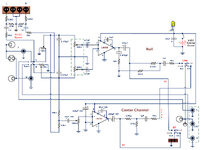
I put together a circuit which is mainly the combination of two circuits I found on websites.
One is for inversion (inverting the left channel, combining it with the right and getting the result).
The other is a center channel.
The designs appeared in several places and seemed to be recognized as correct.
So all I really did was join them and add a bulb and a few switches.

When I connect a small 8 ohm speaker all I get is a hum. And this occurs even without input.
I am using two LM386 ICs which are mounted in sockets (to avoid soldering the IC leads directly).
They're tiny so I had to take care not too short any.
The connections have been tested for continuity (with the leads) and discontinuity (among the socket leads).

Does anyone have any ideas how to go about debugging this?
 

Attachments

  • Inversion.jpg
    Inversion.jpg
    395.5 KB · Views: 121
Hi,

1) you think there is something wrong. And I guess the schematics are from reliable sources. If so, then the issue lies in your wiring.
Thus it´s important to show us your wiring.

2) you say you can hear a hum. This most often comes from mains frequency. Your schematic shows a battery as power supply. But I guess oyu are using an AC/DC adaper, am I right? If so, then this probably is the cause of the hum. Try a battery to verify.
If the battery

****
In either case: for Audio circuits proper wiring, especially a proper GROUND-concept is important.
This is not a simple task, especially when one expect some decent quality.
Regarding quality the almost 50 years old LM386 isn´t the best choice.

Klaus
 
Klaus,

Thank you for your response. Indeed I was using an AC/DC adapter. (It was probably from an old mobile or small appliance.)
I knew it was an AC hum but I never expected it would completely overshadow the output.
Once I replaced the source with a 9V battery it worked great . . . for a while.
I tested with line output from my receiver.
My first test, of course, was an AM radio source. Being intrinsically mono the "inversion" portion would completely attenuate the audio. And it did. The center channel portion was nothing exciting; the audio simply came through.
I then I chose an (FM radio) stereo source. The center channel seemed to work right. But then all of a sudden I heard little pops and crackles which fifty years ago I termed "transistor farts." That meant something was dying.
And indeed the unit did. I also noticed the lamp was dimmer once this occurred.
I can replace one or both of the LM386 ICs. But this can recur.
Do you think I weakened the ICs by initially using that adapter (which actually put out ~15VDC)?
Also, I turned the unit off and brought up the receiver's speakers. Once I removed the input RCA plugs it became louder. Should I put, say, a 2K ohm resistor at the input of each channel?

Roy
 
Hi,

what you call "inversion" and "center" channel, is for me "subtracting" and "adding" respectively, or "difference" and "sum"...

What about the IC temperatures?
What about the individual amplifier outputs?
What about the individual current consumption?

To me it more sounds like a soldering problem, or some mistake ...

Either debug from input in direction to faulty output, or the opposite way.

Klaus
 
The datasheet of the LM386 amplifier shows a "bypass" capacitor at pin 7 to ground. These capacitors are missing in your circuit and their function is to reduce most power supply noise. Add them to reduce the hum from your amplifiers that have their gain much too high (200 times).

The LM386 produces 0.5W into 8 ohms with low distortion when its power supply is 9V but produces only a little more output power when the supply is 12V or more BUT then it overheats when playing loudly.

Klaus
The datasheet of the LM386 amplifier shows a "bypass" capacitor at pin 7 to ground. These capacitors are missing in your circuit and their function is to reduce most power supply noise. Add them to reduce the hum from your amplifiers that have their gain much too high (200 times).

The LM386 produces 0.5W into 8 ohms with low distortion when its power supply is 9V but produces only a little more output power when the supply is 12V or more BUT then it overheats when playing loudly.
Thank you for your response.
I had the 2011 datasheet. I now have the 2023 and see it. In some of the schematic examples the 10uF is shown as non-electrolytic. In the one for the AM receiver it is. Should that matter? That is, I do have two remaining 10uF electro caps. Can I use them or must I get mylar? Also, for pin 7 the sheet states: 10 μF, Pins 1 and 8 Open. Must I remove the cap between pins 1 and 8 (thus losing the extra boost [which isn't the end of the world])?
 
The new datasheet has a graph of power supply noise rejection produced by the bypass capacitor. The power supply hum is at 50Hz to 120Hz so an electrolytic 10uF to 100uF capacitor should be used. This bypass capacitor does not affect extra boost or not.

A server error will not allow me to attach my marked-up graph.
 

LaTeX Commands Quick-Menu:

Similar threads

Part and Inventory Search

Welcome to EDABoard.com

Sponsor

Back
Top