Continue to Site

Welcome to EDAboard.com

Welcome to our site! EDAboard.com is an international Electronics Discussion Forum focused on EDA software, circuits, schematics, books, theory, papers, asic, pld, 8051, DSP, Network, RF, Analog Design, PCB, Service Manuals... and a whole lot more! To participate you need to register. Registration is free. Click here to register now.

[SOLVED] Dead Time in SPWM Motor Control Design

Status
Not open for further replies.

mobinmk

Full Member level 2
Full Member level 2
Joined
May 27, 2010
Messages
140
Helped
4
Reputation
8
Reaction score
4
Trophy points
1,298
Location
Kollam (Quilon),kerala, India
Activity points
2,484
Hi frnds,

am doing project , variable frequency of 3 phase iinduction motor.

succesfully i generated 3 spwm frequency which is 120 deg phase each other.by arduino uno (atmega328 uc) using 3 phase DDS(sine look uptable,timer,interrupt)

SPWM freq is 33khz (carrier frequency).

in order to verify the output of spwm pulses.

output of spwm pulses is fed into 12.5khz low pass chebsyc filter.

filter ckt given below

dds_lowpass1251.jpg

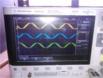
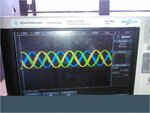
output of filter in dso is
Picture1.jpg

Picture2.jpg

also the freq can vary from 0 -1023hz.

nw i wan to make dead time ckt and invert of 3pulses, so total 6 pulses to 3 phase inverter (6 igbt).

dead time required is 1 or 2us. it depend on the value of R and C of dead time ckt.

i try to design the circuit.
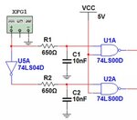
7673937_f1024.jpg

any modification is needed in this ckt ??

pls share your knowledges


regards

mobin
 

With this circuit, you get symetrical delays (rise/fall). For a dead time, you just need to add a delay only at the start of each square waves (for both complementary signals).

Thus you need to put an antiparallel diode across each resistor (cathode toward micro controller). Also, it's better to use NAND gates with schmitt-trigger (hysteresis) inputs, to avoid any parasitic oscillations.

- - - Updated - - -

Actually, you don't even need NAND gates. You could use any schmitt-trigger hex inverters/buffers (like this high-speed IC: SN5414).
 

dead time required is 1 or 2us. it depend on the value of R and C of dead time ckt.

Hi mobinmk

More suitable circuit for deadtime creation , would be schmit trigger not gates and RCD networks . You got the idea or perhaps i should bring you the schematic ?

Best Wishes
Goldsmith
 
should i use ultra fast diode ??
or 1n4007 ??

- - - Updated - - -

Hi mobinmk

More suitable circuit for deadtime creation , would be schmit trigger not gates and RCD networks . You got the idea or perhaps i should bring you the schematic ?

Best Wishes
Goldsmith

would you mind to bring schematic,

input of dead time ckt is

3 spwm pulses from arduino uno

spwm freq is 33khz

dead time required is 2us
 

Ultrafast, of course (you need to discharge the capacitor faster, to avoid any unwanted delay on the falling edge).
 

UF4001-4004 are faster than UF4007 (50ns vs 75ns) but if you only got UF4007 that's OK, too. MUR120 has 25ns, though.
 

You better put the G4 inverter before R2/C2 (like in your first schematic). This way, every RCD circuit is driven by a separate gate output and you could easily design identical delay constants by choosing the same components values (R/C).
 

There's no mistake, as long as you put the inverter G4 after the R2/C2 (like in your last posted schematic).

If you put it before R2/C2, use the same diode position as for R1/C1.

- - - Updated - - -

diode across R1 is not antiparallel ??

It doesn't matter. With the actual D1 position, you've got fast turn-off and delayed turn-on for the output signals.
 

If you put it before R2/C2, use the same diode position as for R1/C1.

Both diode should antiparallel ??

- - - Updated - - -

You better put the G4 inverter before R2/C2 (like in your first schematic). This way, every RCD circuit is driven by a separate gate output and you could easily design identical delay constants by choosing the same components values (R/C).

The delay of the falling edge of OUT1 can be calculated as the
following:


tdout1 = –R1C1ln(Vtl/Voh)

where Voh is the high-level output voltage of the input gate, and Vtl is the low-level trigger
voltage of the Schmitt-trigger. Similarly, the delay of the rising edge of OUT2 is the following:

tdout2 = –R2C2ln(1-Vth/Voh)

where Vth is the high-level trigger voltage of the Schmitt-trigger

rail voltage to NOT gate ,Schmit trigger is 5v.

can i use this eqn ??

dead time required for 1us , value of R,C ??
 

What is you final circuit diagram?

If you put the same signal in front of both delay networks, one diode should be antiparallel and the other one in a straight position.

If you put the inverter G4 in front of the second delay network (R2/C2) both diodes will have the same position.
 

thnks sir.

If you put the inverter G4 in front of the second delay network (R2/C2) both diodes will have the same position.

both diode is paralell across R1 and R2.

ANODE >> OUTPUT OF NOT GATE.
CATHODE >> INPUT OF SCHMIT TRIGGER (JN of R,C,Schmit trigger input.)

pls help me to find the R, C value for 1us dead time
 

Normally with MOSFET input capacitance, all that is needed is Rg//diode gate resistance to turn on slow and turn off fast to get a differential deadband in full bridge. Rg can be calculated. perhaps in the range 1-10 Ohms depending on drain current and max. Ig.
 

He needs fast turn-on/turn-off to lower the switching losses. A slower turn-on it's not equivalent with a dead time.
 

RC (=1us) it's just the time constant (tau). After one time constant, the voltage across capacitor is 0.37 * Vi (Vi = initial capacitor voltage).

To calculate your RC, we have this formula:

RC = t / ln(Vi/Vc), where

t = dead time (1us)
Vi = initial capacitor voltage (Vcc - Vd)
Vc = inverter low threshold (Vtl)

So I need to know what's your Vcc voltage (5V or 15V?) and the low threshold (Vtl) of the schmitt-trigger inverter.
 

vcc = 5 v

1n4148 diode is used,vf = 1v.reverse recovery time is 8ns

vcc-vd = 5-1 =4v

for vth . i made a potential divider across vcc = 5 v by 2 1k resitor so vth = 2.5v

RC = 1us/ln(4/2.5) = 2.12 *10^-6
 
Last edited:

Status
Not open for further replies.

Similar threads

Part and Inventory Search

Welcome to EDABoard.com

Sponsor

Back
Top