ku637
Advanced Member level 4

Hi,
I have a board designed with DDR2. I want to check certain timing parameters in the existing design.Clock Frequency is 150MHz.
I have a oscilloscope Lecroy 620zi 2GHz, 2 Active probes HFP2500 2.5GHz, and one differential probe AP034 , 1GHz.
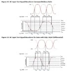
I want to measure the timing specification of DDR2 device MT47H64M16HW like input setup time and hold time shown below,

if i make all single ended measurements as shown in figure 32 it will take 3 active probes which i don't have ( CK,CK#,say 1 Address signal)
So I want to measure the clock CK and CK# with a differential probe. So i will get a single waveform, not two as shown in figure like CK and CK#.
But the concern is in order to measure the setup time and hold time the figure 32 make use of the crossing point of CK and CK# signals , which i wont be getting. So anybody can suggest me if it is possible or what is the correct way?
Thanks,
I have a board designed with DDR2. I want to check certain timing parameters in the existing design.Clock Frequency is 150MHz.
I have a oscilloscope Lecroy 620zi 2GHz, 2 Active probes HFP2500 2.5GHz, and one differential probe AP034 , 1GHz.
I want to measure the timing specification of DDR2 device MT47H64M16HW like input setup time and hold time shown below,

if i make all single ended measurements as shown in figure 32 it will take 3 active probes which i don't have ( CK,CK#,say 1 Address signal)
So I want to measure the clock CK and CK# with a differential probe. So i will get a single waveform, not two as shown in figure like CK and CK#.
But the concern is in order to measure the setup time and hold time the figure 32 make use of the crossing point of CK and CK# signals , which i wont be getting. So anybody can suggest me if it is possible or what is the correct way?
Thanks,

