Continue to Site

Welcome to EDAboard.com

Welcome to our site! EDAboard.com is an international Electronics Discussion Forum focused on EDA software, circuits, schematics, books, theory, papers, asic, pld, 8051, DSP, Network, RF, Analog Design, PCB, Service Manuals... and a whole lot more! To participate you need to register. Registration is free. Click here to register now.

DC to DC VOLTAGE COVERTER

Status
Not open for further replies.

withoutWAX

Newbie level 4
Newbie level 4
Joined
Mar 8, 2013
Messages
5
Helped
0
Reputation
0
Reaction score
0
Trophy points
1,281
Activity points
1,318
Hello guys! I'm needing your help.

How could I possibly convert +45Vdc to +15Vdc using LM7815? Cause as far as I know the max input for the said regulator is limited only to 35V. Is that right?

The same thing for -45Vdc to -15Vdc using LM7915.


Any help would be appreciated much..
:smile:
 

You can use following voltage regulator. Its maximum input voltage 60 V , Adjustable voltage output from 5V to 20V @ 1 A. LM2941T, LM2941S, LM2941LD

If you draw more current it will be heat. you must provide heat sink.

If you want reduce heat . Better you choose switching regulator.

For negative voltage regulator it maximum input voltage 60V. LT117AHV .And others above the same.


http://www.ti.com/lit/ds/symlink/lm2941.pdf

http://www.datasheetcatalog.org/datasheet/irf/om7654sm.pdf

I hope it will helps you.
 
Last edited:

You can use following voltage regulator. Its maximum input voltage 60 V , Adjustable voltage output from 5V to 20V @ 1 A. LM2941T, LM2941S, LM2941LD.

Are you sure about this? Datasheets and articles from the web says that the max input voltage for LM2941 is +26V and is not 60V.

Can anyone verify this?
 

Sorry I made mistake. You can use LM2576HV switching regulator. Its maximum input voltage 60V. refer datasheet.
 

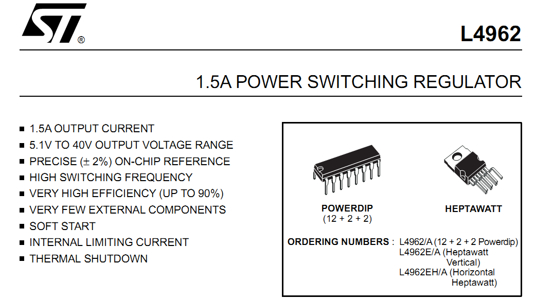
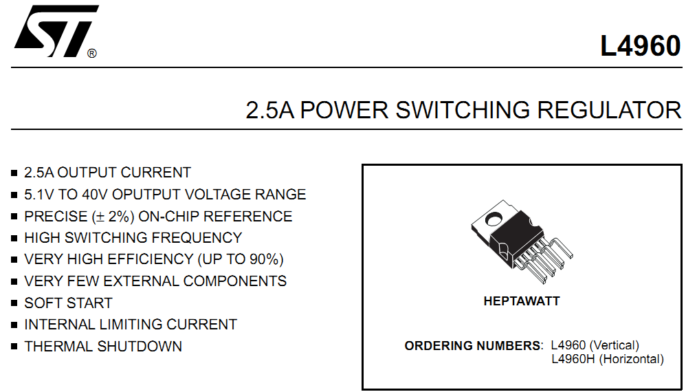
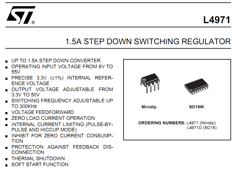
You can take a look at L4971 or L4960 or L4962 as well, depending on current requirement.

3557980400_1362757833.png


8313904200_1362757833.png


2129171200_1362757832.png


You can find the circuits in the datasheets.

L4971:
https://www.st.com/web/catalog/sense_power/FM142/CL1456/SC355/PF63205
Datasheet PDF link: https://www.st.com/st-web-ui/static/active/en/resource/technical/document/datasheet/CD00001355.pdf

L4960:
**broken link removed**
Datasheet PDF link: **broken link removed**

L4962:
**broken link removed**
Datasheet PDf link: **broken link removed**

Hope this helps.
Tahmid.
 
Hello guys! I'm needing your help.

How could I possibly convert +45Vdc to +15Vdc using LM7815? Cause as far as I know the max input for the said regulator is limited only to 35V. Is that right?

The same thing for -45Vdc to -15Vdc using LM7915.


Any help would be appreciated much..
:smile:

What current you plan to have in circuit ?
 

Hello guys! I'm needing your help.

How could I possibly convert +45Vdc to +15Vdc using LM7815? Cause as far as I know the max input for the said regulator is limited only to 35V. Is that right?

The same thing for -45Vdc to -15Vdc using LM7915.


Any help would be appreciated much..
:smile:
If you want to use 7815 and 7915 for regulation, you can use a "preregulator" using a zener-transistor combination. You can bring the 45V down to about 20V and then feed that to the regulator. Keep in mind the required current and thus the power dissipation in the transistor and the regulator, especially since the regulation is based on a linear regulator. A switching regulator like mentioned above by me and amayilsamy as well tends to be more efficient.

Go through this: **broken link removed**

Hope this helps.
Tahmid.
 
You can make simple cascode stacks with discrete Rs
and transistors to drop the headroom in smaller bites,
but dropping this much voltage in a linear regulator is
certain to be wasteful and also give you a lot of waste
heat to manage.

Much better to drop all but 3V in a switcher, and run
your linears off (say) 18V - if you need the linears' low
noise; otherwise, just get a dual output 48V (telecom)
+/-15V output switcher and move on to whatever the
real project is.
 
What current you plan to have in circuit ?

I'm going to use it to supply 3 ICs (op amps), so I think it's almost 15mA.

- - - Updated - - -

Thanks for contributing here guys.
Now I have the ideas to build the supply.

:)
 

For only 15mA, you can quite easily use resistor + zener or zener-transistor combination. You can do without a separate linear or switching regulator.

Power dissipation = (45 - 15)V * 0.015A = 0.45W - that's pretty small and very manageable.

Hope this helps.
Tahmid.
 

For only 15mA, you can quite easily use resistor + zener or zener-transistor combination. You can do without a separate linear or switching regulator.

Power dissipation = (45 - 15)V * 0.015A = 0.45W - that's pretty small and very manageable.

Hope this helps.
Tahmid.

Sure it will.

But now I have confusions about zener diodes. I dont know what current on the datasheets I should use to compute for the series resistor. There are these Izt, Izm, and Izk.

Articles from the web regarding regulators using zeners shows the computation,
Rs = (Vin-Vz)/(Izmin+Iloadmax)

From the currents above which do you think I could use for Izmin?
 
Last edited:

And another thing, what are the differences between Izm, Izk and Izt
 

hi,
you can drop voltage by using voltage divider of 3.3k resistor each for 15mA. Across R2 you will have 22.5V(half of 45V),from here you can use 7815 regulator to have 15V of 15mA.
I hope you know voltage divider.....

Use 2W resistors...
Sorry if I am wrong....
 
  • Like
Reactions: tpetar

    tpetar

    Points: 2
    Helpful Answer Positive Rating
And another thing, what are the differences between Izm, Izk and Izt

Izm is the maximum zener current. If the current through the zener is higher than Izm, the zener will get damaged. Make sure you use a certain "headroom" between the actual current and Izm.

Izt is the zener test current. It's the current through the zener that was used to test the zener voltage.

Izk is the knee current of the zener diode. The change in current increases rapidly at a certain reverse voltage. The change from a low to a high current is sharp and well-defined. This is the zener knee. Izk is the current corresponding to the knee point and is the minimum current the zener must carry to operate in reverse breakdown operation.

Hope this helps.
Tahmid.
 

You can use buck regulator ic lm2576hv adjustable version, datasheet and all other details are available in www.ti.com
free sample version are available from the site.
lm2576 can be operated upto 60v,
there is only few external components are needed
 
  • Like
Reactions: tpetar

    tpetar

    Points: 2
    Helpful Answer Positive Rating
Status
Not open for further replies.

Part and Inventory Search

Welcome to EDABoard.com

Sponsor

Back
Top