zia.newversion
Member level 5

Ok. I am not asking for a PCB footprint for a DC Power Jack since I have searched and seen a few members getting scolded over asking a stupid question which could easily be solved by searching. I already have a PCB footprint of a DC Power Jack. I am using EagleCAD and the schematic is confusing me, partly because I have never used a DC Power Jack before (Yeah, we have a power supply which has croc clips at the power terminals  )
)
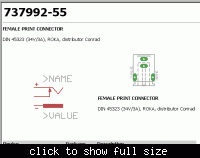
Anyway, the picture of the schematic is attached... Can anyone please explain how a DC power jack works? And where normal power supplies have two terminals, why does it have four? And how would I use this schematic? How can I find out which terminal is V+, which one is V- or GND... Please help. Thank you.
P.S. If anyone is wondering, the schematic AND the footprint came from Sparkfun Library for Eagle.


