icarus1977
Newbie level 6


 Hi all,
I hope this is in the correct section if not could a moderator please move it to the correct section...
Basically I have a small project I am working on, but it's been a few years and I am a bit rusty on my basic principles etc
I have built and have running a lure machine, for dragging a dummy bunny to aid in the training of a bird of prey...
But I need to slow the speed down, at one point it was clocked at 5,600 RPM before we fitted the pulleys so speed may have been increased further, I am happy with the speed except for when I wish to load the spool in which case it's running too fast and following a snag in the line resulted in the spool flying dangerously fast in my direction...
So I was trying to work out a way to slow the motor down, without having to use a mechanical solution...
The motor I am using is a Starter motor (part number is 25092D - M35G), it's running off a 12V Motor Bike Battery.
I have approximated that she is pulling around 40A but are unable to test correctly as my meter is not up to it...
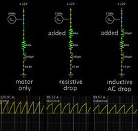
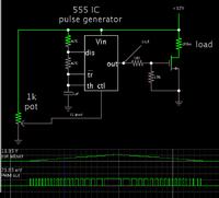
How would I best control the speed of it, would a PWM circuit correctly control the circuit or would it soon burn it out, I thought of a rheostat but it would need to be bulky to handle that sort of current, same as if I used a potential divider circuit...
Any help on this would be greatly appreciated...
- - - Updated - - -
Just found out the following information on the starter motor I am using, hope it's correct...
25092D M35G-12V-0.8Kw STARTER MOTOR AMBASSADOR PETROL 1.5 HM PLUS
So it looks like it's pulling 67A not what I initially thought of 40A...
- - - Updated - - -
So it's a series wound dc motor, so am I right in thinking that I could use a mosfet to control the motor speed using a voltage level shifter on the gate. As I believe a mosfet is not concerned about the size of current passing through it...
Or would a H circuit using transistors work better?
Last edited:


