Continue to Site

Welcome to EDAboard.com

Welcome to our site! EDAboard.com is an international Electronics Discussion Forum focused on EDA software, circuits, schematics, books, theory, papers, asic, pld, 8051, DSP, Network, RF, Analog Design, PCB, Service Manuals... and a whole lot more! To participate you need to register. Registration is free. Click here to register now.

DC motor H bridge current waveform

anotherbrick

Full Member level 4
Joined
Jan 10, 2009
Messages
220
Helped
1
Reputation
2
Reaction score
1
Trophy points
1,298
Location
Istanbul , Turkey
Activity points
3,163
hi dear forum members

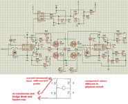
my question in the picture

thank you
current.jpg
 
you are seeing the current flowing into the electro across the fets, when they turn off motor current flows into electro - and source current still flows into electro - but reducing . . . .
 
you are seeing the current flowing into the electro across the fets, when they turn off motor current flows into electro - and source current still flows into electro - but reducing . . . .
If by “electro” you mean capacitor, then I agree. Which is why I asked to see a schematic to begin with…
 
Move the current probe so it only measures the current going to/from the MOSFETs.
I think that will be less confusing.
As you expect in post #1, when switching off MOSFETs 1 and 4, the current goes in MOSFETs 2 and 3 (body diode),
so the current to/from the MOSFETs will change polarity.
 
If - in the real world - you had the electro on the LHS of the current probe in your sketch above, rather than across the H bridge ( where it is but you omitted it from your sketch ) then you would see your expected waveforms.
 

LaTeX Commands Quick-Menu:

Part and Inventory Search

Welcome to EDABoard.com

Sponsor

Back
Top