020170
Full Member level 4

Hello
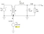
I have studied about spice modeling, especially buck converter.

To realize this schematic, i write netlist like this
VG VIN GND VIN_para
RIN VIN V0 RL_para
V_DC_IN V0 V1 DC 0
F1 V1 GND V_DC_OUT 'N(V(VD,0))'
E1 V2 GND VIN GND 'N(V(VD,0))'
V_DC_OUT V2 V3 DC 0
L0 V3 VOUT 100uH
CL VOUT GND 10uF
RL VOUT GND 100
VD VD GND DC 'VOUT_PARA/VIN_PARA' AC 1
.param N(x)='x'
.param VIN_PARA=12
.param VOUT_PARA=5
.param RL_para=0.1
.tran 1u 10m
.probe V(*) I(V*) I(ROUT)
.AC DEC 100 1m 1G
.probe VDB(VOUT) VP(VOUT) VDB(VD)
.PRINT GAIN=par('V(VOUT)/V(VD)')
.end
in transient simulation, result is correct. but ac simulation, gain and phase is so strange.
in this text book, ac simulation is like this.

bu t my result is not corresponding. I appreciate that there is anyone who can explain about this.
thanks
I have studied about spice modeling, especially buck converter.

To realize this schematic, i write netlist like this
VG VIN GND VIN_para
RIN VIN V0 RL_para
V_DC_IN V0 V1 DC 0
F1 V1 GND V_DC_OUT 'N(V(VD,0))'
E1 V2 GND VIN GND 'N(V(VD,0))'
V_DC_OUT V2 V3 DC 0
L0 V3 VOUT 100uH
CL VOUT GND 10uF
RL VOUT GND 100
VD VD GND DC 'VOUT_PARA/VIN_PARA' AC 1
.param N(x)='x'
.param VIN_PARA=12
.param VOUT_PARA=5
.param RL_para=0.1
.tran 1u 10m
.probe V(*) I(V*) I(ROUT)
.AC DEC 100 1m 1G
.probe VDB(VOUT) VP(VOUT) VDB(VD)
.PRINT GAIN=par('V(VOUT)/V(VD)')
.end
in transient simulation, result is correct. but ac simulation, gain and phase is so strange.
in this text book, ac simulation is like this.

bu t my result is not corresponding. I appreciate that there is anyone who can explain about this.
thanks


