tapu
Full Member level 5

Data transmition serielly by by 8051 through rf module.
Dear All,
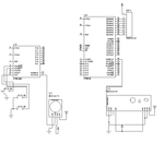
I want to transmit data serielly by using Rf module 433mhz.I have made circuit as follow in proteus.As i press key in transmitter side then data is not seen in reciever 8051 port.pls chk & help.
Thks,
Tepu

Transmitter code:
Reciever code:
Dear All,
I want to transmit data serielly by using Rf module 433mhz.I have made circuit as follow in proteus.As i press key in transmitter side then data is not seen in reciever 8051 port.pls chk & help.
Thks,
Tepu

Transmitter code:
Code:
//-----------------Program for wireless Home Automation using cheap ass 413MHz RF module
//-----------------Target controller family: 8051 <works for any 8051 family with minimal or no modifications>
//-----------------Programmer: Moses Okoroafor
//-----------------Company: Pearl Electronics Nigeria.
//-----------------Date started: 27/04/2017


#define OFF 1
#define ON  0
#include <REGx051.H>


 //-----------PORT TO VARIABLE ASSIGNMENT--------------------------
sbit BUT1 = P3^2;
sbit BUT2 = P3^3;
sbit BUT3 = P3^7;
sbit LED1 = P3^5;
sbit LED2 = P3^4;

//-------------PROTOTYPE DECLARATION-------------------------------
void delay(unsigned int ms);
void UART_Init();
void UART_TxChar(char ch);
void transmit(int datum);
bit i,j,k;

//-------------MAIN PROGRAM STARTS HERE----------------------------
void main()
{
	i = j = k = 1;
	EA = 0;

	P1 = 0X3F; P3 = 0XFF;                    // shows '0' on the 7 seg on startup
	delay(300);
	LED1 = LED2 = ON;
	delay(1000);
	LED1 = LED2 = OFF;
	delay(100);
	UART_Init();

	while(1)
{
 if (!BUT1)                                           //button for one light
    {delay(30);
      if(!BUT1)
			{
				j = ~j;
				if(j==0)
       { transmit(0x01); LED1 = ON;  if(k==0) P1 = 0X5b; else P1 = 0x06;}               //when bits are 0, lights come ON
				 else {transmit(0x09);LED1 = OFF; if(k==1)P1 = 0X3F; else P1 = 0x06;}
				delay(300);
			}
		}


if (!BUT2)                                           //button for the second light
    {delay(30);
      if(!BUT2)
			{
				k = ~k;
				if(k==0)    {transmit(0x03); LED2 = ON; if(j==0)P1 = 0X5B; else P1 = 0X06;}                          //lights ON
				else     {transmit(0x06); LED2 = OFF;   if(j==0)P1 = 0x06; else P1 = 0X3F;}
				delay(300);
			}
		}


if (!BUT3)                                         // reset
    {delay(30);
      if(!BUT3)
			{
				i = ~i;
				if(i==0) {transmit(0x02); LED1 = LED2 = ON; }
				else     {transmit(0x0F); LED1 = LED2 = OFF;}
				delay(300);
			}
		}


}
}


//---------------FUNCTION BODY DEFINITION--------------------------------------

void delay(unsigned int ms){                      //generate one millisecond delay
  unsigned int i,j;
  for	(i=0; i<ms; i++)
  for   (j=0; j<=120; j++);}


	void UART_Init(){
	TMOD |= 0X20;                       // Timer 1 in mode 2
	TH1=-24;                            // Baud rate of 1200
	SCON = 0X50;                         //Asynchronous 8-bit data
	TR1 = 1;                             // Turn ON the timer
                }


  void UART_TxChar(char ch){
	SBUF=ch;           // Load transmitted data to be transmitted.
	while(TI==0);      // Wait till data is transmitted
	TI=0;              //Clear the transmit flag.
}


void transmit(int datum){
	int i = 0;
	int start  =  0x55;             // Create a variable name START
	int addr   =  0x8E;              //  Create a variable name ADDR

	int chksum =  (addr+datum);            //   Create a variable name CHKSUM

		for (; i<5; i++)

		{

		UART_TxChar(start);           // Transmit the content of START
		UART_TxChar(datum);           // Transmit DATUM
		UART_TxChar(addr);            //Transmit ADDR
		UART_TxChar(chksum);          // Transmit CHKSUM
		delay(2);                      //2ms delay

    }
	}
Reciever code:
Code:
//-----------------Program for wireless Home Automation using cheap ass 413MHz RF module
//-----------------Target controller family: 8051 <works for any 8051 family with minimal or no modifications>
//-----------------Programmer: Moses Okoroafor
//-----------------Company: Pearl Electronics Nigeria.
//-----------------Date started: 27/04/2017


#define OFF 1
#define ON  0
#include <REGX52.H>


 //-----------PORT TO VARIABLE ASSIGNMENT--------------------------
sbit LED1 = P1^0;
sbit LED2 = P1^1;


//-------------PROTOTYPE DECLARATION-------------------------------
void delay(unsigned int ms);
void UART_Init();
char UART_RxChar();
void receive();


//-------------MAIN PROGRAM STARTS HERE----------------------------
void main()
{
		LED1 = LED2 = ON;
	delay(1000);
	LED1 = LED2 = OFF;
	delay(100);
	UART_Init();

	while(1)
	{
		receive();
	}
}


//---------------DEFINITION OF FUNCTIONS----------------------------------


void delay(unsigned int ms){                      //generate one millisecond delay
  unsigned int i,j;
  for	(i=0; i<ms; i++)
  for   (j=0; j<=120; j++);}


void UART_Init(){
	TMOD |= 0X20;                       // Timer 1 in mode 2
	TH1=-24;                            // Baud rate of 1200
	SCON = 0X50;                         //Asynchronous 8-bit data
	TR1 = 1;                             // Turn ON the timer
                }


	char UART_RxChar()
{
	char ch;
	while(RI==0);
	ch = SBUF;
  	RI=0;
	  return(ch);             // Return the received character.
}


 void receive()                   //   Receive procedures
	{
int start;	 	// create variable named start
int addr;   	// create variable named addr
int datum;		// create variable named datum
int chksum; 	// create variable named chksum

while(1)               // Do an infinite loop
{


    { start = UART_RxChar();        			// Store received UART byte into the variable "start"
	if (start == 0x55)                      // if start is equal to 0x55 , Start Byte
 		{
		 SBUF =0;                              //clear SBUF
		 datum = UART_RxChar();			          //Next received byte becomes the data
		 SBUF =0;                            //clear SBUF
		 addr = UART_RxChar();               // Store received UART byte into the variable "addr"

        	SBUF =0;                    //clear SBUF
		chksum = UART_RxChar();

			if (chksum == (datum+addr))                //if chksum is equal to datum+addr then
			{
				switch(datum)
					{
						case (0x01):  { LED1 = ON; }         break;
						case (0x02):  { LED1 = LED2 = ON;}   break;
						case (0x03):  { LED2 = OFF;}         break;
					  case (0x0F):  { LED1 = LED2 = OFF;}  break;
						case (0x09):  { LED1 = OFF; }        break;
            case (0x06):  { LED2 = ON; }         break;
						}


					}                                  //endif for switch statement
			}                                     //endif
		}                                      //endif
}

}
Last edited by a moderator:
