Vermes
Advanced Member level 4

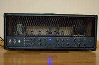
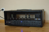
It is a construction of Custom 50W Hi-gain head.
Assumptions:
- power: approximately 50W on EL34 tubes in PP system
- three channels with almost separate tube chains
- Clean: Fender channel
- Crunch: in Marshall style, but slightly changed
- Lead: hi-gain in Slo style, but changed – a copy of lead channel from CAE 3+se preamp
- Fx Loop
- digital channel control
- possibility of quick change the volume level
- opportunities to develop the tone of sound and high universality
- fit as much as possible on the PCB
- reduce the number of cables
- high quality and aesthetics
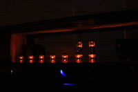
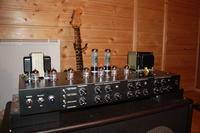
- uses 9 tubes including 7 triodes
Housing:
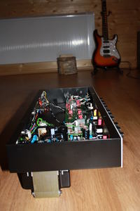
Chassis was made of 1mm plate by a company. The design was made in Autocad (3D + viewports). The box was made of 18mm plywood, lined with derma, with corners of amptone.
PCBs:
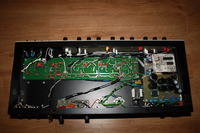
PCBs of the power supply, Bias, Fx Loop, potentiometers and digital control were designed and made in thermal transfer method. Paths were tinned by plating. PCB of the preamplifier was made by a company. It has two layers, metallized, tin plated and has two-sided soldermask.
Front panel:
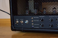
Front panel was designed in Autocad and then in Corel.
Digital support system:
Everything is supported by small 5V relays. Relays and LEDs supported from separate control board. Main element is microcontroller Atmega8 programmed in Bascom and driver of relays ULN2803, which can replace some other components on the PCB. The principle is quite simple: foot switch shorts a given led of Atmega to the ground for a moment, causing change of its state from 1 to 0, what sends signal to the driver, etc. This is a great alternative to logic systems and is very universal – it can support 1 to 8 relays. The system is powered from a separate transformer inside the housing.
Power supply:
Power supply has nets and anode supply, it is equipped with separate sources of voltage for groups of triodes of different functions. A fuse and capacitors were used. There are also capacitors on 10A bridge.
Power amplifier:
It was based on a schematic of inverter and feedback loop of the mesa ninety with a significant number of „switches” for example for power reduction. EL34 tubes, which operation point is 40-45W were used in this project. Bias from a separate winding can be set separately for both tubes.
Preamplifier:
Preamplifier was inspired by x88r, but with other chains. It uses relays, three of them are on Lead channel. In addition, tonestacks were slightly modified. The number or cables was reduced, and in result, all potentiometers are placed on the PCB, which is also very convenient. Voltage on tubes anodes are almost the same as in simple x88r (in Lead channel – slightly lower: 10-20V). Triodes are placed on stands soldered into the PCB, glow is also on the PCB.
Fx Loop:
Effect loop is mosfet loop. It is placed behind the last common stage of gain in the preamplifier. Remember to add the right input resistor and capacitor on a by-pass, so the loop can maintain its transparency.
Pictures:

Link to original thread - Custom 50W Hi-gain Head by Recon