Continue to Site

Welcome to EDAboard.com

Welcome to our site! EDAboard.com is an international Electronics Discussion Forum focused on EDA software, circuits, schematics, books, theory, papers, asic, pld, 8051, DSP, Network, RF, Analog Design, PCB, Service Manuals... and a whole lot more! To participate you need to register. Registration is free. Click here to register now.

Current Transducer LTS 25np Circuit Design

Status
Not open for further replies.

afiqaris

Newbie level 3
Newbie level 3
Joined
Mar 31, 2013
Messages
4
Helped
0
Reputation
0
Reaction score
0
Trophy points
1,281
Activity points
1,313
i have this problem understanding this circuit from my fellow senior friend in school,.(graduated)

with his permission,im using LTS25np current transducer to monitor load on GUI for my SCADA project.

so i need to create a circuit with this transducer.i used his as reference and a stepping stone.

can someone pls help and explain the design output of the transducer. why are there two diodes in parallel and what is the Capacitor and resistor there for?

from what i understand,the inputs to the CT are live of applied load of 1-8A and transformer Vin. And the CT uses 5vcc supplied from the voltage regulator.

PLS help,tqvm.
 

Attachments

  • Current Transducer.png
    Current Transducer.png
    48.9 KB · Views: 210

can someone pls help and explain the design output of the transducer. why are there two diodes in parallel and what is the Capacitor and resistor there for?
At first sight, the diode circuit seem like a perfect way to ruin the accuracy of the high perfomance current sensor. It doesn't seem to serve a reasonable purpose. I can only guess that the circuit is an almost failed attempt to make an AC measurement with a DC current sensor. But it should use a precision rectifier circuit instead of a simple diode rectifier that exposes non-linearity and temperature dependant offset.
 
At first sight, the diode circuit seem like a perfect way to ruin the accuracy of the high perfomance current sensor. It doesn't seem to serve a reasonable purpose. I can only guess that the circuit is an almost failed attempt to make an AC measurement with a DC current sensor. But it should use a precision rectifier circuit instead of a simple diode rectifier that exposes non-linearity and temperature dependant offset.

IC, so what you are suggesting is to improvise the output design of the CT with a precision rectifying circuit.

would you mind suggesting me any specific approach. Im majoring in IT and this is all new to me.

My project is to create a SCADA system with HMI display for monitoring a transformer. Hence, fabricating a circuit would help me a lot in terms of gained knowledge.

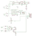
here i have attached a full schematic of my senior friend project. His was roughly the same but without SCADA and HMI.

Probably, may you kindly look into the schematic and comment freely on anything you find bizarre.

PLEASE, i appreciate very much the feedback. thank you.

every day is a learning process to rookie like me
 

Attachments

  • full schematic.jpg
    full schematic.jpg
    36 KB · Views: 117

Status
Not open for further replies.

Part and Inventory Search

Welcome to EDABoard.com

Sponsor

Back
Top