Continue to Site

Welcome to EDAboard.com

Welcome to our site! EDAboard.com is an international Electronics Discussion Forum focused on EDA software, circuits, schematics, books, theory, papers, asic, pld, 8051, DSP, Network, RF, Analog Design, PCB, Service Manuals... and a whole lot more! To participate you need to register. Registration is free. Click here to register now.

Current Amplification Problem

Status
Not open for further replies.

rahdirs

Advanced Member level 1
Joined
May 22, 2013
Messages
424
Helped
93
Reputation
192
Reaction score
91
Trophy points
1,308
Location
Mordor
Activity points
4,492
Capture.JPGPower.JPGHi everyone,

At the output of my circuit i have an opamp that gives out 12V & 10mA,but the next stage that my circuit drives needs 12V & 5A,how do i provide this current amplification.

Thought of using buffer circuit so that output impedance is low increasing current,but it didn't work.
Used IC 741 as Voltage follower for buffer circuit


Regards,
rahdirs
 
Last edited:

i donot think there is a ready IC that will be the trick.

my guess is to go to a class AB amplifier using BJT transistors. Assuming you know how to do that.

note that this extra current amplified will not be created from nowhere ! it should be available for the amplifier as power ( 12x 5= 60W ) in your supply circuit .

hope that helps
 

1.

I agree that a class AB is needed for you to obtain 5A and 12V output.

2.

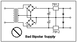
Although it may look as though the two diode bridges ought to cooperate, to provide a bipolar supply...

There is a short circuit during one half of the cycle.
 

Thank You, BradtheRad but some ppl tell me that the circuit that i posted in 1st post is wrt what i want to do.

Here's what i want to do,
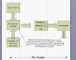
I have a varying voltage source that varies between 0V & 12V providing 7A current.I have to make it to a constant 12V so that i can up convert it to 220V AC and use it power devices(storing my ckt 12V o/p in a battery bank & then an inverter to produce 220V AC).

So,what i did was down convert grid voltage 220V Ac to 12V DC.I then subtract the two voltages(grid voltage - varying voltage),then i added the gradient between the two voltages to the varying voltage so that i get a constant 12V o/p,now i up convert this 12V o/p to 220V AC.

The reason i can't use grid to bring the o/p current to 5A is i want to use varying voltage source to power my battery bank.


Is it true that my circuit cannot do the above operation,can u suggest ny other way to do this

What i want to do is xplained in attached next 2 images

Capture1.JPGCapture2.JPG
 
Last edited:

why don't you use a DC-DC converter ? buck-boost probabaly the way to go , i have designed such circuits . without the need for 220v mains AC.

another thing i donot understand how is 0v providing 7A ?!!

if the varing voltage is from 4-12 or whatever it could be done as i said before .
 

Do you intend to have the PV panels charge the battery during blackouts? Then you need to keep the mains AC charging separate from the PV charging/conversion.

It will be cumbersome to devise a way to supplement a 6V deficiency in the PV panel, by adding 6V from mains AC.

Your system will be constructed from several sub-systems. It is best if you create the solar charger/controller as one unit, and the mains converter/charger as another unit. Later, you can add a changeover switch, etc.

---------------

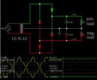
This screenshot shows how to obtain a bipolar supply from a center-tapped transformer.


It only needs 4 diodes. No short-circuits occur.

The website below discusses the problem of your initial bipolar supply.

https://mysite.du.edu/~etuttle/electron/elect9.htm

Image from website (scroll down about 90%).

9914318300_1369363251.png
 
  • Like
Reactions: rahdirs

    rahdirs

    Points: 2
    Helpful Answer Positive Rating
@BradtheRad,@Electro nS : I tried using class AB by using two complementary BJTs but i am still getting currents in the range of 1-2A,can u suggest a way to make it 5-7A(i even tried cascade connection).

I used class B in the schematic as there will be no cases of cross-over distortion.
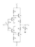
Do i need to use Class-AB Output Stage with Input-Buffer Transistors as in fig.1???


I observed that Power MOSFETs gave faster switching speeds in place of BJTs as expected from theory,and MOSFETs being high impedance devices reduced effort on previous stages,so MOSFETs are better than BJTs for my circuit.
But seeing the less usage of Power MOSFETs over BJTs on net,are there any design disadvantages associated with Power MOSFETs.
Capture.JPGCapture.JPG
 
Last edited:

In the schematic in the attached link, i am getting a current amplification of about 90 from 11 mA to 1 A. But i need current amplification of about 500 so that i can get 12-13 V at 10 A.

I tried darlington configuration in class AB & also Class-AB Output Stage with Input Buffer Transistors as given in Sedra & Smith but am still not getting 10 A.
Then i connected the 2 class AB amplifiers of same configuration as in schematic so that i can get double current at same voltage. But what i found was that current by each amplifier reduced by half to generate same current.

So can I conclude that the input impedance of the circuit beyond the point indicated in the schematic prevents current from going beyond 2 A at 12 V & that input impedance when of the next stage when looking from this point is, 12 V/2 A = 6 ohm. I hope that i am wrong.:wink:

Thanks,
rahdirs
 
Last edited:

1.

If you don't obtain 7A, there are any number of reasons.

* Power supply has insufficient current.

* Transistor bias lacks sufficient amplitude and/or current.

* Intervening components with high resistance.

* Thin wires. (To carry 7 A you should use 14 or 16 gauge)

* Poor connection(s).

2.

A transistor bias is referenced to the emitter terminal.
For an NPN, its bias current needs to see a definite return path to the more negative part of the bias loop.
For a PNP it is to the more positive part of the bias loop.

3.

Is your 741 providing a range of output which fully turns on and off your transistors?
 

@BradtheRad,@Electro nS : I tried using class AB by using two complementary BJTs but i am still getting currents in the range of 1-2A,can u suggest a way to make it 5-7A(i even tried cascade connection).

I used class B in the schematic as there will be no cases of cross-over distortion.
Do i need to use Class-AB Output Stage with Input-Buffer Transistors as in fig.1???


I observed that Power MOSFETs gave faster switching speeds in place of BJTs as expected from theory,and MOSFETs being high impedance devices reduced effort on previous stages,so MOSFETs are better than BJTs for my circuit.
But seeing the less usage of Power MOSFETs over BJTs on net,are there any design disadvantages associated with Power MOSFETs.
View attachment 91596View attachment 91579

if you plan to use power mosfets , then prepare for nightmares interms of driver circuit and ESD protection + sparks and a lot of smoke :)
BJTs are simpler and easier to control . if the BJTs are not providing the suffcient current , you might be using a low current BJT or not baising it correctly , as you know you need to supply current at the base enough for the transistor to open . i will at your schematics and see if i might find whats wrong

- - - Updated - - -

In the schematic in the attached link, i am getting a current amplification of about 90 from 11 mA to 1 A. But i need current amplification of about 500 so that i can get 12-13 V at 10 A.

I tried darlington configuration in class AB & also Class-AB Output Stage with Input Buffer Transistors as given in Sedra & Smith but am still not getting 10 A.
Then i connected the 2 class AB amplifiers of same configuration as in schematic so that i can get double current at same voltage. But what i found was that current by each amplifier reduced by half to generate same current.

So can I conclude that the input impedance of the circuit beyond the point indicated in the schematic prevents current from going beyond 2 A at 12 V & that input impedance when of the next stage when looking from this point is, 12 V/2 A = 6 ohm. I hope that i am wrong.:wink:

Thanks,
rahdirs

the current from the 741 opamp is not suffeint since beta =approximatly 10 in these transistor , check datasheet page 2 figure 2 . my suggestion is to try to use different Darlington pnp , and npn .(just change transistors) ,they have huge current gain . try it and tell me what happens

cheers
 

Status
Not open for further replies.

Part and Inventory Search

Welcome to EDABoard.com

Sponsor

Back
Top