Continue to Site

Welcome to EDAboard.com

Welcome to our site! EDAboard.com is an international Electronics Discussion Forum focused on EDA software, circuits, schematics, books, theory, papers, asic, pld, 8051, DSP, Network, RF, Analog Design, PCB, Service Manuals... and a whole lot more! To participate you need to register. Registration is free. Click here to register now.

Cubic spline interpolation - need a maths whiz to explain it to me.

Status
Not open for further replies.

boylesg

Advanced Member level 4
Joined
Jul 15, 2012
Messages
1,023
Helped
5
Reputation
10
Reaction score
6
Trophy points
1,318
Location
Epping, Victoria, Australia
Activity points
11,697
I understand the idea of control points - a start coordinate for the spline, an end point for the spline and a coordinate each for the top/bottom of all the curves.

I get that the formula for a cubic equation is Y = aX3 + bX2 + cX + d

I get the concept of derivatives in calculus.

So the first derivative of a cubic equation has the form of Y = 3aX2 + 2bX + c and the second derivative has the form Y = 6aX + 4b.

So I remember from maths in the 80s that the derivative of a quadratic equation will give you the gradient of the curve at any point X.

So I assume the second derivative of a cubic equation similarly gives you the gradient of the curve at an point X?

Question 1: What does the first derivative of a cubic equation tell you about the curve if the second derivative gives you the gradient at any point X?

Question 2: How do you use the second derivative to calculate a series of lines that define a close match to the curve given an iteration interval between two control points?

Question 3: Given the control points, how do you work out the cubic equation that you can then work out the derivatives from?

I have been trying to understand the process from written tutorials but have been finding it confusing. Perhaps a diagramatic description of the process would be easier to 'get'.
 

So I remember from maths in the 80s that the derivative of a quadratic equation will give you the gradient of the curve at any point X.
The gradient or more exactly, the slope of the tangent line. But it's not specific to quadratic functions, it's true for any function, e.g. cubic. Respectively the succeeding assumption is wrong.
 

2nd derivative of a function (f'') gives you knowledge of the curvature of the original function (f) (i.e. convex when f''(x)>0 or concave when f''(x)<0). Also gives you knowledge of the inflexion points (if any) that the original function (f) has.

That is all what f'' can tell about f.

- - - Updated - - -

Question 3: Given the control points, how do you work out the cubic equation that you can then work out the derivatives from?
Pretty standard, I think. Just solve a 4x4 system (easiest way is using determinants). Wiris can help you: **broken link removed**

- - - Updated - - -

Question 2: How do you use the second derivative to calculate a series of lines that define a close match to the curve given an iteration interval between two control points?
Integration.
 

All your questions from post #1 were answered, do you still have questions ?
 

All your questions from post #1 were answered, do you still have questions ?

I am completey stuck I am afraid.

I followed this explanation of Bezier curves (https://medium.freecodecamp.org/nerding-out-with-bezier-curves-6e3c0bc48e2f) and I had a quite good understanding of it by the end. I get the B(t)x and B(t)y forumulas for deriving the line segments that make up the curve.

I am reading my control points from a DFX file and here are a couple of sample splines from the DFX file below.

'10' followed by a floating point value is the 'X' axis, '20' followed by a floating point value is the 'Y' axis and '30' followed by a floating point number is the 'Z' axis. Z axis is always 0 since it is a 2 dimensional PCB design.

And there always seems to be 4 control points for all the splines in the DFX file.
However my code has incomplete provision for splines with greater than 4 control points, for what it was worth.

The rest of the 'SPLINE' details seem to be fairly irrelevant for a 2D PCB design. For example '72' followed by 8 tells you that the spline as 8 x knots. '40' followed by an integer tells you the value of each of the 8 x knots. These are always 1 or 0. I have read that 'knots' are the same thing as 'control points'. So I have no idea what purpose 'knots' serve in this particular DFX file.

'73' followed by '4' tells you that there are 4 control points and there are indeed 4 x sets of floating point x,y,z coordinates for each SPLINE in the sample DFX contents. So this is the only important information about the SPLINES in this particular DFX file.

Code:
SPLINE
  5
4E
100
AcDbEntity
  8
Layer_1
  6
ByLayer
 62
    7
370
   -1
100
AcDbSpline
210
0
220
0
230
0
 70
    8
 71
    3
 72
    8
 73
    4
 74
    0
 42
1e-007
 43
1e-007
 40
0
 40
0
 40
0
 40
0
 40
1
 40
1
 40
1
 40
1
 10
66.89290099999999
 20
0.159256
 30
0
 10
66.58310299999999
 20
0.28965
 30
0
 10
66.055547
 20
0.611722
 30
0
 10
65.72051999999999
 20
0.875231
 30
0
  0
SPLINE
  5
4F
100
AcDbEntity
  8
Layer_1
  6
ByLayer
 62
    7
370
   -1
100
AcDbSpline
210
0
220
0
230
0
 70
    8
 71
    3
 72
    8
 73
    4
 74
    0
 42
1e-007
 43
1e-007
 40
0
 40
0
 40
0
 40
0
 40
1
 40
1
 40
1
 40
1
 10
65.72051999999999
 20
0.875231
 30
0
 10
65.124989
 20
1.343684
 30
0
 10
64.73791799999999
 20
1.354371
 30
0
 10
48.357153
 20
1.354371
 30
0
  0


This is my code for calculating the line segments that form a curve defined by 4 x control points contained in 'arrayCtrlPnts'.
nSplineType always seems to be 8, for planar spline, and nSplineDegree always seems to be 3.

Assume that the remainder of my code is only concerned with extracting the SPLINE control points from the file.

I have tested this thoroughly and I am definitely getting the correct floating point values in each element of arrayCtrlPnts - parameter of function BezierCurve(...)

Code:
class CFloatPoint
{
    public:
        CFloatPoint();
        CFloatPoint(CFloatPoint& point);
        virtual ~CFloatPoint();

        CFloatPoint &operator =(CFloatPoint &point);
        operator CPoint&()
        {
            static CPoint point;

            point.x = (int)round(m_fX);
            point.y = (int)round(m_fY);

            return point;
        };

        float m_fX, m_fY;
};

float cube(const float fVal)
{
    return fVal * fVal * fVal;
}

float square(const float fVal)
{
    return fVal * fVal;
}

// CFloatPointArray is defined as typedef CArray<CFloatPoint, CFloatPoint&> CFloatPointArray 
// CArray is one of the MFC template collection classes.
// CArray objects are used much like a regular CArray except that they are dynamic without requiring you to implement all the memory 
// allocation and deallocation.
// You index them like a regular C array but you can add elements to the end via CArray::Add(...).

// CStringArray is defined as typedef CArray<CString, LPCSTR> CStringArray;
// This array is filled by function BezierCurve(...) with simple text instructions that I transmit over UDP serial to my Arduino based CNC engraver.
// "MT" means 'move to' and it is followed by an x,y coordinate.
// "LT" means 'line to' and it is followed by an x,y coordinate as well as a percentage density which used to PWM the laser. I have envisaged using the laser 
// engraver to engrave images as well as PCBs.
// I am then using this array of Arduino instructions to render the PCB design in the windows app.


void CGregsLaserEngraverDlg::BezierCurve(const byte nSplineType, const byte nSplineDegree, CFloatPointArray &arrayCtrlPnts, CStringArray &arrayFormatted)
{
    if (nSplineType == 8/*Planar spline*/)
    {
        if (nSplineDegree == 3 /*Cubic spline*/)
        {
            CFloatPoint point;
            CString strCode;

            strCode.Format("MT,%f,%f", arrayCtrlPnts[0].m_fX, arrayCtrlPnts[0].m_fY);
            arrayFormatted.Add(strCode);

            // For both X and Y
            // B(t) = (1-t)^3P0 + 3(1-t)^2tP1 + 3(1-t)t^2P2 + t^3P3
            for (float fT = 0; fT < 1.0f; fT += 0.1f)
            {
                point.m_fX = (cube(1.0f - fT) * arrayCtrlPnts[0].m_fX) + (3 * square(1.0f - fT) * arrayCtrlPnts[1].m_fX) + (3 * (1.0f - fT) * square(fT) * arrayCtrlPnts[2].m_fX) + (cube(fT) * arrayCtrlPnts[3].m_fX);
                point.m_fY = (cube(1.0f - fT) * arrayCtrlPnts[0].m_fY) + (3 * square(1.0f - fT) * arrayCtrlPnts[1].m_fY) + (3 * (1.0f - fT) * square(fT) * arrayCtrlPnts[2].m_fY) + (cube(fT) * arrayCtrlPnts[3].m_fY);
                strCode.Format("LT,%f,%f,100", point.m_fX, point.m_fY);
                arrayFormatted.Add(strCode);
            }
        }
        else
        {
            AfxMessageBox("Spline degree not implemented", MB_OK);
        }
    }
    else
    {
        AfxMessageBox("Spline type not implemented", MB_OK);
    }
}

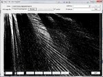
This is what I get when I try to draw all the individual lines:
bezier.jpg
There are actually valid PCB trace outlines buried under all that.
The correct outlines come from 'POLYLINES' that are also in the DFX file.
But clearly I am doing somethign fundamentally wrong with the way I am calculating the line segments in the 'SPLINE' curves.
But I don't understand what I am doing wrong.

I don't see any value in pasting the rest of my code in here as it is all irrelevant windows stuff and DFX file stuff.
I don't need help in interperting what all the contents of the DFX file.
And the forum won't let me attach other than valid image files anyway.

- - - Updated - - -

I don't have to do any calculation with 'POLYLINES' - the coordinates are just read from file and draw.
 

Attachments

  • GregsLaserEngraver.zip
    7.6 KB · Views: 132
Last edited:

The first derivative gives the gradient of the tangent to a point on the curve. The second derivative gives the gradient of the tangent to a point on the curve of the first derivative. And so on...

If you mark the solutions to the first derivatives of the curve on a graph paper with increasing values of x then you get a new curve. This curve is dy/dx.

If you find the derivative of dy/dx and mark points of its solutions on the graph paper with increasing values of x, you get d2y/dx2 when you connect the points.

And so on...

Hope this answers your question.
 

SPLINE
5
4E
100
AcDbEntity
8
Layer_1
6
ByLayer
62
7
370
-1
100
AcDbSpline

All the stuff between SPLINE and AcDbSpline is rendering information - layers, colors and line weight etc.
It is all irrelevant for the purposes of my project and I am ignoring it all.
 

You are stating in post #6
I don't need help in interpreting what all the contents of the DFX file.
So why are you posting and commenting all the dxf stuff that doesn't seem to be related to the original question?
 

Status
Not open for further replies.

Part and Inventory Search

Welcome to EDABoard.com

Sponsor

Back
Top