Continue to Site

Welcome to EDAboard.com

Welcome to our site! EDAboard.com is an international Electronics Discussion Forum focused on EDA software, circuits, schematics, books, theory, papers, asic, pld, 8051, DSP, Network, RF, Analog Design, PCB, Service Manuals... and a whole lot more! To participate you need to register. Registration is free. Click here to register now.

Crystal oscillator using discrete CMOS inverter ?

Status
Not open for further replies.

joeypc

Newbie
Newbie level 3
Joined
May 28, 2008
Messages
3
Helped
0
Reputation
0
Reaction score
0
Trophy points
1,281
Activity points
1,328
Hello Everybody,

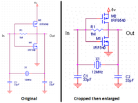
I built a discrete CMOS inverter as shown below:

upload_2015-5-2_23-28-31.png


This CMOS inverter worked as an logic inverter very well. But when I tried to apply to crystal oscillator as below. It did not work at all! Could anyone here explain why ? Thanks all.
upload_2015-5-2_23-28-52.png
 

A CMOS inverter, like 74HC04, has Cin of ~ 10 pF, whereas these MOSFETs in the 1000+
pF range.

Just totally suppresses loop G of the oscillator.

At 12 Mhz you could create a osc out of CMOSW gate, then drive a MOSFET driver
stage to drive your power stage.


Regards, Dana.
 
  • Like
Reactions: joeypc

    joeypc

    Points: 2
    Thank you for your kind reply.
Those FETs' Cdg may be killing the loop gain @freq, Miller negative feedback in parallel with the xtal quasi-LC?

Try a small signal transistor or maybe a model for the single stage inverters of CD4000 (if below 1Mhz) or 74xxx families if you can find).
 
  • Like
Reactions: joeypc

    joeypc

    Points: 2
    Thank you for your kind reply.
The transistor/mosfet half-bridge tends to stagnate when we try to use it in a crystal-driven oscillator.
However with an inductor (CLC shape) the transistor half-bridge does oscillate.

The mosfet half-bridge lacks snap action, whereas an invert-gate does have it. Therefore the single invert-gate is sufficient to make a crystal-driven oscillator. (And that's what we often see demonstrated for crystals.)
 
  • Like
Reactions: joeypc

    joeypc

    Points: 2
    Thank you for your kind reply.
Beside the points already mentioned, you didn't tell if you discuss a real hardware or simulation problem.
Dear FvM,

This kind of discrete MOSFETS inverter has been built, tested by me on solderless breadboard. From what I see is that it works quite like a normal C-MOS inverter. This C-MOS inverter is supplied with +5V. Output of this inverter is connect to 220 Ohms resistor then to a LED and to ground to test logic level. When I connect input of inverter to VCC, the Led is off. When I connect input of this inverter to ground, the led shine bright. When I connect nothing at the input, the led dim. When I touch the input of this inverter with my finger, it affect the brightness of the led. When I connect 1 Mega ohms resistor at the input and the output of this inverter to try to bias as a linear amplifier, the led dim. But when I try to add 12 Mhz crystal and loading capacitors as shown in the first post of this thread, it does not oscillate at all. By the way, thank you all for your kind replies.
 

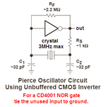
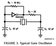
A CD4xxx or 74HCxx Cmos logic IC has tiny little Mosfets that have extremely LOW input capacitance.
Also, they fully turn on with an input of 3.1V above 0V for N-Mos or 3.1V below the + power supply voltage for P-Mos.

Your IRF power Mosfets have input capacitance that is extremely HIGH. A crystal oscillator needs very low capacitance parts and wiring.
They fully turn on with an input of 10V above 0V for N-Mos or 10V below the + power supply voltage for P-Mos.

Why are you using high power, high input voltage and high input capacitance Mosfets?
 

Attachments

  • Cmos crystal oscillator.PNG
    Cmos crystal oscillator.PNG
    12.2 KB · Views: 214
  • crystal oscillator.PNG
    crystal oscillator.PNG
    7.8 KB · Views: 200
  • Like
Reactions: joeypc

    joeypc

    Points: 2
    Thank you for your kind reply.
At 12MHz, the input capacitance of your power Mosfets are a dead short and they will not oscillate in your crystal oscillator.
The wiring and rows of contacts on a solderless breadboard might be to high for a Cmos IC crystal oscillator at 12MHz.
 

Attachments

  • power Mos oscillator.png
    power Mos oscillator.png
    35.6 KB · Views: 213
  • Like
Reactions: joeypc

    joeypc

    Points: 2
    Thank you for your kind reply
Status
Not open for further replies.

Part and Inventory Search

Welcome to EDABoard.com

Sponsor

Back
Top