Continue to Site

Welcome to EDAboard.com

Welcome to our site! EDAboard.com is an international Electronics Discussion Forum focused on EDA software, circuits, schematics, books, theory, papers, asic, pld, 8051, DSP, Network, RF, Analog Design, PCB, Service Manuals... and a whole lot more! To participate you need to register. Registration is free. Click here to register now.

Crowbar Circuit problem

Status
Not open for further replies.

pscammp

Newbie level 6
Newbie level 6
Joined
May 25, 2016
Messages
11
Helped
0
Reputation
0
Reaction score
0
Trophy points
1
Activity points
164
Hello all,

I need help with a crowbar circuit I'm currently constructing.

I am using some MC3423's (you don't see these very often anymore) as the basis of the circuit and the datasheet is as follows:

https://www.onsemi.com/pub_link/Collateral/MC3423-D.PDF

Circuit is based on the following schematic although 'R1' is replaced by a 50k variable pot:

https://www.google.co.uk/search?q=M...MAhUG1hQKHR2lAFEQsAQIKQ#imgrc=xbodhPXdUWl9iM:

I am also planning on using the following Thyristor to act as the crowbar device, datasheet again as follows:

https://www.farnell.com/datasheets/112558.pdf

Power to the crowbar circuit is supplied from the output of a variable Buck/Boost DC-DC converter set to output 12VDC and a 3A circuit breaker is on Vcc before the crowbar circuit, the voltage divider is set to get pin 8 on the IC to fire between 13.0v and 13.1v which has been fine tuned with the Pot in place of R1. Up to this point I have a 470 ohm resistor from Pin 8 to an LED and then to Vee purely as a visual indicator for the crowbar activating which has allowed me to get the trip voltage where I want it at approx. 13v.

I'm no electronics expert by far so here's my problem:

I have no clue how to work out what the value of the resistor 'Rg' should be to work with my chosen Thyristor. I see figures in the Thyristor's datasheet and the IC's datasheet but Pin 8 is pumping out around 12.38v when Vtrip is reached at 13.0 - 13.1v. From what I can see the Thyristor's gate wants only 1.0v (1.5v max) and 9mA typical.

I'm 80% lost here, it makes a bit of sense but I haven't a clue how to get there, the closest I could got was a 1.2K resistor which gives me 10.3mA (or does it ?) using Ohm's law I = V / R. But, is this right ? If it is then how does that 12.38v get below 1.5V for the Thyristor's gate ??

HELP !

Thanks so much for any help which may be offered
Paul
 

The "typical" gate trigger current is supposed to be around 10mA at 25C, but the worst case trigger current is quoted as being as high as 30mA at 25C and up to 75mA at ultra low temperature.

Now you don't want it to only just work, you want to be absolutely sure it is going to always work.
So a design trigger point might be something like 50mA.
As the trigger supply voltage is going to be up near +12v minus the actual gate voltage, a resistor around 200 ohms or 180 ohms would be my choice.
Its not going to be that critical, but give it heaps of gate current to be certain the most insensitive SCR is going to work on a cold frosty morning.
 
Last edited:

Hey Tony,
Thanks for the reply, I really appreciate it.

I have 5 DC-DC outputs in total, x3 at 12v, x1 at 14v and the last at 19.5v, I shall base each crowbar as close to 50mA as possible into their respective SCR Gates as you suggest.

The 12v outputs will be tripping at approx. 13v

The 14v output will be tripping at approx. 15v

The 19.5v output will be tripping at approx. 21.5v

Quote - "+12v minus the actual gate voltage" -
What is this 'gate voltage', cant seem to see mention of it in the data sheet, is this what gets the 12.38v down to the allowable limits of 1.0v Typical to 1.5v Max ?

Many Thanks again Tony

Paul
 

Gate voltage is just one diode drop maybe 0.7v or something...
Its pretty low, but if you were building a 3.5 volt crowbar, it starts to become significant enough to take into account.

It does not need to be exactly 50mA but something around that.
A bit more or less to fit in with a commonly available standard resistor value will be fine.
The crowbar chip has plenty of available output current, so no worries there.
 

Great,

Thanks again for your time Tony.

I'll let you know how I get on when I get a chance to hook up the Thyristor's for the big finale.

Paul
 

Hi Tony,
Latest progress........I do have one slight problem !

Working on one of my 12v circuits:

I set up the Potentiometer to a value in the voltage divider which allows the IC to trip between 13.0 - 13.10v using an LED initially and all works fine. I have measured the voltage coming out of Pin 8 of the IC at the moment of Trip which was 12.39v. I worked out what Rg's value to the Gate of the SCR should be in the following way:

R = V / I
R = 12.39v / 0.050mA

R = 247.8 Ohm's

I settled on a 1% tolerance resistor at 220 Ohm's which gives me a Current into the Gate of about 56mA

So I have hooked up the thyristor into the circuit today in the way shown in the circuit diagram linked at the top of this thread with an Rg value of 220 Ohm's, when I power up the circuit it pretty much immediately blows the circuit breaker, I have checked and from what I can make out the IC is not firing though.

What I did then was power down, reset the circuit breaker, disconnected the Gate on the SCR from the circuit (Anode and Cathode is still connected), powered it up again and the circuit powers up fine as I have a 12v LED connected across Vcc and Vee now as an indicator of 'power's up' and the LED was now lit. At this point, I reconnected the 'Gate' and all seemed stable. Slowly raising the output voltage from the DC-DC indeed caused the circuit breaker to trip between 13.0v and 13.10v

So, Obviously the whole crowbar circuit receives the 12v supply all at once and I know it is functioning correctly due to the test I did detailed above so my question is this:

Any Idea why when power is first applied the circuit breaker is blowing ???

Many Thanks
Paul

- - - Updated - - -

Ok so I have been doing a little more investigation......

With the circuit powered up with 12v:
With the SCR's gate disconnected and the 220 Ohm resistor floating from Pin 8 of the IC there is approx. 40 - 50mV coming out of Pin 8 according to my digital multimeter. If I then allow the SCR's Gate to touch the 220R resistor this drops all the way to zero. Disconnecting the gate then see's the mA come up again

Could I somehow be getting a big enough 'spike' on the Gate on connecting the power enough to fire the SCR ????

Just an uneducated guess !

Regards
Paul
 
Last edited:

THe dv/dt applied across the SCR (at hard start) can cause it to turn on, so either a cap on the gate, or a snubber across the SCR main terminals, or both...
posting a circuit would help....

- - - Updated - - -

also have a close read of the data sheet for delayed tripping,, C1 across R2, fig 5.
 

I implemented a crowbar circuit many years ago, and he biggest pitfall is nuisance tripping.

Good layout, good decoupling, and a high dv/dt SCR are required to avoid that
 

Easy P. has the answer, nuisance tripping is a common problem with these types of circuits.

Two cures, first fit a 100 ohm resistor between gate and cathode of the SCR.
That will hardly effect gate current as the 0.7v gate voltage will only rob about 7mA from your 56mA.
But it will greatly reduce the effect of dV/dT tripping due to fast voltage rise on your dc bus.

The other cure is delayed turn on by fitting a suitable capacitor as mentioned in the application notes.
 

Hello all,

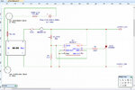
Thanks for the help, just to be completely clear about this, here is a representation of the basic circuit:

Circuit.jpg

Will this 100 ohm resistor connect to the SCR's cathode on the Gate side of R3 ?????

Many Regards
Paul
 

OK,

Scrub/Ignore my last post as there is an error in the circuit diagram, here is the correct one....Sorry:

Circuit_1.jpg

As you'll see I have added the 100 ohm resistor between gate and cathode (in the correct place I assume).

Note 'Con_1' in the diagram, this is a panel mount XLR connector on the main case for each output. A 16.5A cable then plugs into this connector to take power to each piece of equipment. The crowbar circuits will live in a small box on this plugin cable near the XLR connector.

Latest Situation:
Fitting the 100 ohm resistor didn't work, it still tripped the circuit breaker....BUT....I have discovered something useful and 'Con_1' mentioned above is the key.

The Vcc and Vee outputs of each of the 6 DC-DC's as well as going off to their relevant outputs also spur off to a double pole 6 way break before make rotary switch. All 6 Vcc's go to one of the wafers and all the Vee's go to matching pins on the second wafer.

The 'Common' pins on each wafer are connected to a simple digital volt meter in the box with a SPST toggle switch breaking the Vcc to the volt meter. This enabled me to select each output individually to confirm output voltage is correct before connecting the equipment. Once I have confirmed all voltages are correct I would then (while the DC-DC's were live) connect the XLR connector ! ! !

Bare in mind my Crowbar circuits will be built into the cables near the XLR connector, on plugging this in the crowbar gets belted with 12v immediately. What I discovered is that if the main power switch for the circuit (S1 in the schematic) is off and the DC-DC is not powered up, plugging in the XLR first and then turning on 'S1', the DC-DC doesn't immediately hit 12v output but it rises to 12v slowly although still within a fraction of a second though, it's enough to see on the voltmeter.

So what I did was ensure the output was set at 12v, turned OFF the main power switch (S1), plugged in the XLR and then turned on S1 - Crowbar circuit is now NOT tripping the circuit breaker and the LED is illuminated to indicate power is up. I can only assume that when the DC-DC first gets powered up the output voltage comes up slowly enough that it is within the limits of the SCR's dV/dT thing !

Am I thinking on the right lines here ????

Once successfully powered up I raised the output voltage on the DC-DC unit and....**CLICK**....Circuit breaker tripped when output voltage passed 13.0v

Weather or not I will still need this 100 ohm resistor or not remains to be seen but I will probably leave it in anyway.

Hopefully I'm good from here on in with all your kind help people....Thank you

Paul
 

It may still be prudent (as pointed out in #7) to put a small cap in parallel to the 100E resistor as suggested so as to reduce false triggering...
 

Every SCR has an "anode gate" and a "cathode gate".
Either can trigger it. Usually only one is pinned out, and
you may not get to know how well shunted the other is.
So you're left with shunting the one you -can- get at,
and dealing with the other by component selection
based on "what works" and hope the recipe doesn't
change.

There's also an issue that the gate terminal may be way
more effective at triggering than at preventing it; the
former just needs -anything- to light up, the latter that
no place at all in the big device sees stronger dV/dt
current and weaker distributed shunt access than the
transient trigger threshold.
 

Paul, you are on the right track with this.
Some further experimentation may be beneficial now that the false triggering mechanism is understood.
 

@ Dick, for some production reason almost all SCR's these days are cathode gate (current goes into the gate and out the cathode to fire) and finding Anode gate SCR's is rare (for back to back AC switches - see IXYS) whereas in the early days almost all SCR's were anode gate, possibly the hassle of finding the extra few volts needed to turn on an Anode gate SCR (above the anode volts) was the reason for this...
 

Paul, you are on the right track with this.
Some further experimentation may be beneficial now that the false triggering mechanism is understood.

I'm no electronics technician or engineer so all the chips are stacked against me really, all I have is an inquisitive and sometimes
logical mind, a digital multimeter, lots of patience and tutorials on line which I am currently trawling through to get an understand-
ding of what I'm playing around with here.


What I can do at this point is present the facts based on observations with very limited equipment and experience to move forward
with, so with that in mind, this is the situation thus far:

If the 'Gate' of the SCR is connected to R3 when an instantaneous 12v is applied, the SCR fires. If the Gate is NOT connected to R3
but the Anode and Cathode is still connected to Vcc and Vee respectively then it does not fire. This tells me that applying 12v insta-
ntaneously to the Anode/cathode is not causing this firing, the problem has to reside with the Gate itself.

With the Gate disconnected from R3 and a multimeter connected to Vee and Pin 8 of the MC3423, the multimeter does not seem to
register any kind of voltage spike on Pin 8 when applying 12v to the circuit which might be enough to fire the SCR's Gate, instead
the Pin 8 output seems to creep up to between 40-50mV and hover around there. Obviously this 40-50mV will not be enough to fire
the Gate in itself.

With the circuit running below Vtrip threshold (connecting the SCR's gate AFTER the power has been applied) the extra 100 ohm resistor
between Gate and Vee takes the 40-50mV leak from Pin 8 towards zero so I see what this component is doing.

The fact that Pin 8 on the IC is NOT showing evidence of a voltage spike on 'power up' on the multimeter (I wonder if an oscilloscope would
tell a different story ???) also tells me that the 'power up' should not be causing a momentary problem with the voltage divider part of the circuit
which might activate Pin 8 momentarily......Although !

Considering the equation in the MC3423's datasheet:

Formula.jpg

The Vref figure of 2.6v - I also wondered if when the IC first powers up that this 2.6 reference voltage used in the formula might take
'X' amount of time to stabilize and may be lower for a certain amount of time. The resistance of R1 and R2 are effectively constants
whereas Vref may not be. With this I used the formula using 1.0v as Vref, with the R1 and R2 values I got around 4.5v which is not
enough to fire Pin 8 into action. The other side of the coin though, Vref COULD be higher momentarily before it stabilizes which might
open a whole new can of worms ! Unfortunately no one can put a probe on the little device inside the IC to really see what it is doing
when I suddenly hit it with 12v, I can only go by what the output Pin 8 tells me.

I don't really want to put a delay into the mix before the IC activates as it seems to destroy the whole purpose of this circuit in the first
place for my desired results although the datasheet does have suggested stuff for a delayed firing of the IC.

So here we are. It seems I need to concentrate the battle at the trench between IC Pin 8 and the dreaded gate. Again, im no technician or
engineer so this is where I need your help guy's.

I will continue this on a separate reply as this wont seem to allow me to upload another image

Cheers
Paul

- - - Updated - - -

Hello All again,

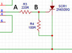
Consider the 'A' and 'B' positions marked either side of the 220R resistor in the following pic:

Gate.jpg

Options:
1. Connecting a capacitor from Vee to position 'A'

2. Connecting a capacitor from Vee to position 'B'

What effect would each position have on this link to the gate ! Lets use a grossly high value cap here so the effect is massively over exaggerated which
might make it easier for me to grasp.

Another option:
Disconnect the 100R resistor from the cathode and place the same cap between 100R and the cathode creating a resistor/capacitor bridge from the Gate
to the cathode (or Vee if you like)

This is a bit like a voltage divider I believe although not the same obviously, what effect would this have if no cap was to 'A' or 'B' ???

Sorry to be a pain guy's, I'm learning here....Honest !

Many Regards
Paul
 

I'm no electronics technician or engineer so all the chips are stacked against me really, all I have is an inquisitive and sometimes logical mind, a digital multimeter, lots of patience and tutorials on line which I am currently trawling through to get an understanding of what I'm playing around with here.

Do not worry, you are in good company!

Let me try to explain:

Sudden application of voltages can have unexpected results in many cases. You cannot see such effects on a simple DMM- they are often elusive even on a scope that are the best bets for such cases.

let us say that 12V has been applied suddenly (within a microsecond or less; yes, they have to be fast sometimes). The SCR has several internal junctions that act like capacitors and they are charging up. The MC3423 is not yet ready and the pin 8 voltage is undefined. If the gate of the SCR is not connected to the ground via the 100E, the gate potential will be undefined.

The internal layers of the SCR act as capacitors and they share and divide the applied potential. It is *possible* the the gate layer gets a potential that can turn on the SCR. It is a crude explanation but broadly accurate (I have skipped some details) - this can cause a false triggering.

If the gate is tied to ground, via the 100E, this potential is defined at all times because the resistor does not need any setup time.

If there is a capacitor too (in addition to the resistor), the capacitor will be charging via the 220E and that may take some time (couple of microseconds is fine) and the gate driver will get ready in that time. Hopefully your circuit will survive some overvoltage for a couple of microseconds.

The delay should be sufficient to get the rest of the circuit ready and operational. This capacitor should be connected as "Connecting a capacitor from Vee to position 'B' in your diagram" because the purpose of the capacitor is to delay the potential on the gate by a couple of microseconds.
 

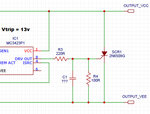
put 100nF 50V across R4, your problems will most likely disappear...
 

c_mitra,

Many thanks for taking the time to explain all that, it makes sense which is a good thing. So, does this look right ?

ZZ.jpg

LOL @ Easy peasy,

That was going to be my next question, you must be psychic !

Ok so I am seeing the following one in my local store:

• 100nf
• Multilayer metallised polyester film capacitor
• Epoxy resin sealed in a flame-retardant thermoplastic case
• Highly reliable and stable over a very wide temperature range (-40°C to +85°C)
• Voltage working: 64Vdc

Would this fit the bill ?

Many Thanks
Paul
 

Status
Not open for further replies.

Part and Inventory Search

Welcome to EDABoard.com

Sponsor

Back
Top