Continue to Site

Welcome to EDAboard.com

Welcome to our site! EDAboard.com is an international Electronics Discussion Forum focused on EDA software, circuits, schematics, books, theory, papers, asic, pld, 8051, DSP, Network, RF, Analog Design, PCB, Service Manuals... and a whole lot more! To participate you need to register. Registration is free. Click here to register now.

Crank dynamo to charge AA battery circuit?

Status
Not open for further replies.

A-E-I-Owned-You

Newbie level 4
Newbie level 4
Joined
Aug 23, 2011
Messages
7
Helped
0
Reputation
0
Reaction score
0
Trophy points
1,281
Activity points
1,341
Crank dynamo to charge AA battery?

I would like to be able to charge one AA Nimh battery with a hand crank dynamo. I am having trouble finding anything useful, so I came to this forum for help! Hopefully you guys can lead me in the right direction. Thanks in advance!

2-3 amps is my general goal by the way.
 
Last edited:

one suggestion i can think of is the mechanism in a'hand cranked radio'

search in 'philips' radios and many chinese make also exists.

google for 'hand cranked radios'. you will get lot and buy one take out the mechanism and start diy...

you can takeout the cranking mechanism and try to use it .
i have not come across any detail on that so far .

so you measure the voltage and adjust accordingly.
and your requirement calls for a power of 3 to 4w generated one.
 
For a good performance and long life, NiMH cells require a well regulated voltage from a charging source. A crank generator usually has a wider-ranging voltage which cannot be applied directly to such sensitive battery.
I would find a commercial charger, measure the typical voltage on charged battery. Then check the DC voltage from AC rectifier. Between the DC input and DC output to a charged battery, there usually is a voltage regulator. Such regulator may be a resistor with a Zener, or an integrated circuit.
If the DC input voltage to the above regulator is similar to what your crank generator generates, you can connect it to the charger.
Otherwise you should design another voltage regulator to battery specifications, or, possibly rewind your crank generator to obtain a matching voltage.
 
I have already taken one crank mechanism out of a flashlight. I plan to find a place to buy JUST the motor and crank as one unit with gears somewhere later. I am trying to get the dynamo to recharge the battery. I know I will need to regulate the power into my NiMH battery, but I do not know how to do that in the least. I will read over what was posted here and see if I can make something work. Does anyone have any links that will point me in the right direction with getting the crank to recharge the battery? :)
 

I guess what I am ultimately trying to do, is figure out what I need to do OVERALL to recharge a NiMH battery with a hand crank dynamo. I am open to any and all suggestions to achieve that including a new dynamo and stuff. The one I have was just to test the theory. Now I want to do it all again with new parts so that I can crank the dynamo and get some sort of charge to the battery as cheap as possible. I assume I need some sort of circuit between the dynamo and battery, just no clue what I would need. Also, dynamos put out random amount of amps and stuff, so I would need to know what I should look for when I buy a new one so I can achieve my goal of recharging the one AA battery.
 

Cheapest rugged way of charging NimH was done by creating a voltaic cell .Dip a carbon rod /copper rod in a acidic/saline solution and derive the 1.5VDC across terminals .Just leave it for some time ,stir it ,and your AA cells charge .
 

if you have already got the dyno mechanism , you are about to reach your goal.

have a voltmeter connected to dynamo output.

just crank .starting from slow winding to faster.
note the voltage range of variation.
then you can design your charger control.

also , try to measure the current delivered by dynamo in a separate expt by connecting a suitable resisitor.
 

I cannot make the cell you describe vimalkhanna due to the project in mind.

There are many types of resistors, right? Which one should I try out? I actually was not able to get the dynamo to produce ANY results on the multimeter, but other tests show that there IS power of some sort coming out of it as it lights up light bulbs rather bright. So what type of resistor is my first question, and my second is, how to test the dynamo with my multimeter (as in which setting) and last, what point am I looking for for a jump off point for the charger control?
 

put your multimeter in 20volt ac range.
give the output of your dyno to com and v terminals.

measure the output.
 

I have the model listed below and it doesnt appear to have a 20volt ac setting, although maybe I am missing it? Also, my dynamo has 3 red wires coming out of it. Should I ground off of a known ground and just apply the positive lead to the 3 red wires?

**broken link removed**
 

when you rotate the switch to clockwise from 'off' position the first one is AC voltage range. put it in any one of the two ranges.

three red wires coming out of dyno ?

i think you are referring the dyno with lighting circuitry connected .

cannot see why three wires red?
 

HI,
Best is put a snap of your dynamo here so we can suggest you easily what you need.
 

The dynamo came from a crank flashlight, yes. I am attempting to find a location online to purchase a crank dynamo that is NOT part of a flashlight but just the unit itself. That way, I can get the parts I need to do what I need. Any ideas of where to find JUST the motor and crank without it being in a flashlight?

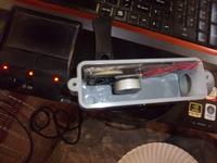
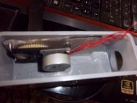
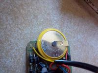
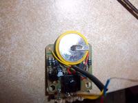
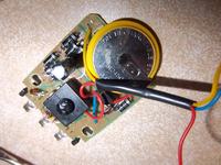
Here is a picture of the crank mechanism in the project enclosure I am using. I also took pictures of the battery and circuitry that came with the rest of the flashlight. The battery is a 3.6v lion with a model number of: LIR2450. It will not do what I want, but maybe showing the battery that was originally used can help you help me! :)


seen the photos . are the red color wires goes to the three pins to a black box shown in photo5 ?

can you trace the circuit from pcb ?
 

The three red wires go to (i think) a group of transistors. They are on the left side in the center of the board in all of those pictures.

Do you just want a picture of the underside of the board or something?
 

i mean the circuit traced from the board.

instead better connect a voltmeter to two terminals of the three and carnk and note the voltage reading.

in that way you can go ahed with your requirement.

you can just mark each terminal and take any two out of three and you will have 3 sets .
measue.
 

Status
Not open for further replies.

Part and Inventory Search

Welcome to EDABoard.com

Sponsor

Back
Top