Continue to Site

Welcome to EDAboard.com

Welcome to our site! EDAboard.com is an international Electronics Discussion Forum focused on EDA software, circuits, schematics, books, theory, papers, asic, pld, 8051, DSP, Network, RF, Analog Design, PCB, Service Manuals... and a whole lot more! To participate you need to register. Registration is free. Click here to register now.

Counting pulses from external source PIC16F877a

Status
Not open for further replies.

Daljeet12

Member level 4
Member level 4
Joined
Jun 16, 2018
Messages
78
Helped
0
Reputation
0
Reaction score
0
Trophy points
6
Activity points
648
I have pic16f877a and MPLABX8 and I want to count pluses generated by encoder

sensor and encoder output is connected to input of PIC and LED is connected to output of PIC

I want to write program for following statement

if the sensor is active, an encoder will generate pulses and microcntroller will count pulses upto 32000 then turn on LED

I am using TMR1 to count pulses on pin RC0

Code:
#define _XTAL_FREQ 20000000 //Specify the XTAL crystall FREQ
 
#define  LED   RB2
 
#define  ON        1
 
void main()
{
   TRISB=0X00; //PORTB pins are used as Output.
   TRISC=0Xff; //PORTC pins are used as Input.
   TMR1H=0x82; // initial count values in timer1 register
   TMR1L=0xff;
   TMR1IE=1; //Enable timer interrupt bit in PIE1 register
   GIE=1; //Enable Global Interrupt
   PEIE=1; //Enable the Peripheral Interrupt
   TMR1ON = 1; //Start Timer1
   T1CON=0x01;   //Prescale value = 1:1, It using Internal clock, Timer 1 ON
}
void interrupt timer_isr()
{
     if(TMR0IF==1) // Timer flag has been triggered
    {
           LED = on
   
           TMR0IF=0;       // Clear timer interrupt flag
    }
}


Please someone help me to make program ?
 

Comments:

You don't start with the LED turned off.
Nothing counts the pulses.

I suspect you want to configure the INT0 interrupt rather than TMR0 so it triggers an interrupt on transitions of the INT pin. From there is a simple case of counting the interrupts (count up a variable inside the ISR) and when it reaches 32000 turn the LED on. Have a think about what happens next though, do you want some way to turn the LED off again?

Brian.

In my original project I am not going to use LED. I am using airjet if the sensor triggred encoder will generate pulses I have to count upto 32000 and then trigreed air jet

Will you suggest me some ideas how it can be done ?
 

First you need to tell a little more specification:

Counting up to 32000 then enabling the air jet is easy but what happens next?
Does the jet stay on for ever or does something turn it off?
What turns it off?

Brian.
 
Your 'main' function has no infinite loop. Therefore your code will never work. Don't forget that this is an embedded system - there is no operating system for your code to return to.
As I think you are using XC8, the runtime used by that compiler will detect that the 'main' has exited and will perform a reset and start the app - so it will just be continuously looping through this process and doing nothing.
Apart from that, as a general rule you should fully configure a peripheral before you turn it on. The last 2 lines of your 'main' code should possibly be the other way around but the setting of the T1CON register as a whole should probably not also turn on the timer.
If you want to count external pulses then T1CONbits.TMR1CS needs to be set to 1. Leaving it a 0 will cause the timer to count from the internal system clock (Fosc/4).
Defining your own meanings for ON (and OFF), especially with ON defined as 1, will cause problems when you include the CONFIG settings in your code (as you should always) - for often unstated but good reasons, the default setting for most CONFIG options is OFF but this equates to the value '1'.
Timer1 on this MCU is of the old design where you set the initial TMR1x registers with the initial count and it then counts *UP* until it rolls over from 0xffff to 0x0000 and sets the xxIF flag. You have this part right. However in the ISR the counter is back to 0x0000 and so you need to reset the TMR1x registers again if you want the same count of 32,000 to be repeated.
Susan
 
Hi,

I wonder why you first talked about a LED, then about airjet.
Why not about airjet from the beginning? ... this just brings confusion.
Technically I see no difference.

Klaus
 

First you need to tell a little more specification:

Does the jet stay on for ever or does something turn it off?
What turns it off?

Brian.
air jet will be turn on only for 50ms

so whenever sensor triggered encoder will generate pulses when it reaches 32000 air jet would be on for 50 ms

- - - Updated - - -

Hi,

I wonder why you first talked about a LED, then about airjet.
Why not about airjet from the beginning? ... this just brings confusion.
Technically I see no difference.

Klaus

Because I don't have airjet available so I thought I should test the program with led
 

I think something like this

Code:
#include<pic16f877a.h>

void main()
{    

    TRISB=0X00; //PORTB pins are used as Output.
    TRISC=0Xff; //PORTC pins are used as Input.
	
    TMR1H=0x82; // initial count values in timer1 register
    TMR1L=0xff;	
    TMR1IE=1;       //Enable timer interrupt bit in PIE1 register
    GIE=1;          //Enable Global Interrupt
    PEIE=1;         //Enable the Peripheral Interrupt
    TMR1ON = 1;     //Start Timer1    

}

void interrupt timer_isr()
{  
    if(TMR1IF==1)
    {
        
        TMR1IF=0;       // Clear timer interrupt flag
    } 
}
 

I'm not sure who found my previous post useful but I doubt if it was the OP as the code written above contains none of the fixes I mentioned that will be required to make it work.
The above code is just a cut-down version of the code first posted.
Are we just wasting our time here? Or is what we are saying not making sense - in which case the OP needs to go back to the very basics such as 'flash a LED' (the embedded equivalent to 'Hello World') to understand the fundamentals of writing embedded code.
Susan
 

Susan,
Speaking as a moderator, we do see many "I found it on the internet, it was for EL34 beam tetrodes but I converted it to work on a PIC" postings. For you and I, we can see they are heading off on the wrong course and ignoring the direction signs but for a complete novice who expects to be led by the hand they find it difficult to see the destination, let alone the way to reach it.

Brian.

I am not ignoring the advice actually I am new for PIC I don't know which interrupts would to use to count encoder pulses timer or external interrupt

Once I will be sure than I can try to make program if I get any problem I will be post here

which interrupts would to use to count encoder pulses timer or external interrupt ?
 

The INT pin on the PIC is the safest way to count, it uses the external interrupt functionality.

You might be able to use an ordinary input/output pin if the count pulses are relatively slow. To do that all you have to do is continuously loop while reading the pin (polling) and look for it's logic state changing. However, using external interrupts is always safe and can respond faster because the detection is in hardware rather than software.

Look at the INT/RB0 pin which will be your count input then look at the interrupt sections on the data sheet to see how to configure for detecting external interrupts. Inside your ISR you need to add a variable (declare it as "volatile unsigned int xxxxx;" where xxxxx is the name you choose for the counter) and add one to it. After adding one, see if it has reached 32000 and if it has, set another variable to indicate the count has been reached then exit the ISR. In your main() routine keep checking to see if the indicator is set and if it is, turn your air jet on.

Brian.
 
Hi,

The INT pin on the PIC is the safest way to count, it uses the external interrupt functionality.
This is a good solution if you want the software to count the pulses.

But you may use T1CKI to directly make the hardware to count pulses.
This is the fastest way to count pulses ... and it needs no interrupt, no ISR and no processing power for the counting.

Klaus
 

The INT pin on the PIC is the safest way to count, it uses the external interrupt functionality.

You might be able to use an ordinary input/output pin if the count pulses are relatively slow. To do that all you have to do is continuously loop while reading the pin (polling) and look for it's logic state changing. However, using external interrupts is always safe and can respond faster because the detection is in hardware rather than software.

Brian.

spending few time on google I made below program I know It's not complete but started and compiled

This program compiled successfully
Does it make any sense for further help
Code:
// CONFIG
#pragma config FOSC = HS        // Oscillator Selection bits (HS oscillator)
#pragma config WDTE = OFF       // Watchdog Timer Enable bit (WDT disabled)
#pragma config PWRTE = OFF      // Power-up Timer Enable bit (PWRT disabled)
#pragma config BOREN = ON       // Brown-out Reset Enable bit (BOR enabled)
#pragma config LVP = OFF        // Low-Voltage (Single-Supply) In-Circuit Serial Programming Enable bit (RB3 is digital I/O, HV on MCLR must be used for programming)
#pragma config CPD = OFF        // Data EEPROM Memory Code Protection bit (Data EEPROM code protection off)
#pragma config WRT = OFF        // Flash Program Memory Write Enable bits (Write protection off; all program memory may be written to by EECON control)
#pragma config CP = OFF         // Flash Program Memory Code Protection bit (Code protection off)

#include <xc.h>

#define _XTAL_FREQ 20000000 //Specify the XTAL crystall FREQ

void main(void) 
{
    
    TRISB0=1;     // Make RB0 pin as input
    TRISD1= 0;    // Make RD1 pin as output
    OPTION_REG=1;  // Set Rising Edge Trigger 
    INTCON = 1;   // Enable The Global Interrupt
    INTF = 1;     // External Interrupt Enable 
    
    while (1)
    {
        
    }
    return;
}

void interrupt isr(void)
{  
    if(INTF==1)
    {
        
               // Clear interrupt flag
    } 
}
 

Tidied up a little and with the counting and checking added:
Code:
// CONFIG
#pragma config FOSC = HS        // Oscillator Selection bits (HS oscillator)
#pragma config WDTE = OFF       // Watchdog Timer Enable bit (WDT disabled)
#pragma config PWRTE = OFF      // Power-up Timer Enable bit (PWRT disabled)
#pragma config BOREN = ON       // Brown-out Reset Enable bit (BOR enabled)
#pragma config LVP = OFF        // Low-Voltage (Single-Supply) In-Circuit Serial Programming Enable bit (RB3 is digital I/O, HV on MCLR must be used for programming)
#pragma config CPD = OFF        // Data EEPROM Memory Code Protection bit (Data EEPROM code protection off)
#pragma config WRT = OFF        // Flash Program Memory Write Enable bits (Write protection off; all program memory may be written to by EECON control)
#pragma config CP = OFF         // Flash Program Memory Code Protection bit (Code protection off)

#define _XTAL_FREQ 20000000 //Specify the XTAL crystal FREQ

volatile unsigned int MyCounter;
char MyTrigger;

void main(void) 
{
    
    TRISB0=1;     // Make RB0 pin as input
    TRISD1= 0;    // Make RD1 pin as output
    OPTION_REG=1;  // Set Rising Edge Trigger 
    INTCON = 1;   // Enable The Global Interrupt
    INTE = 1;     // External Interrupt Enable (not INTF)

    MyCounter = 0;  //initial values at start up
    MyTrigger = 0;
    
    while (1)
    {
        if(MyTrigger == 1)
        {
            // put the code to operate the air jet here
        }
    }
    return;
}

void interrupt isr(void)
{  
    if(INTF==1)
    {
        INTF = 0;  // Clear interrupt flag
        MyCounter++;    // add 1 to the MyCounter
        if(MyCounter == 32000) MyTrigger = 1;
    } 
}
Note that this can be improved but it will give you some idea of how to do it. You can also use the direct counting method Klaus suggested but this method will give you some insight on how interrupts work. I have not tested the code or even tried to compile it!

Brian.
 
Tidied up a little and with the counting and checking added:
I have not tested the code or even tried to compile it!

Brian.

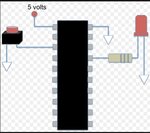
I don't have air jet so I am checking code with LED and Push button

I have tested the following code

external interrupt.jpg

Code:
 // PIC16F877A Configuration Bit Settings

// 'C' source line config statements

// CONFIG
#pragma config FOSC = HS        // Oscillator Selection bits (HS oscillator)
#pragma config WDTE = ON        // Watchdog Timer Enable bit (WDT enabled)
#pragma config PWRTE = OFF      // Power-up Timer Enable bit (PWRT disabled)
#pragma config BOREN = ON       // Brown-out Reset Enable bit (BOR enabled)
#pragma config LVP = OFF        // Low-Voltage (Single-Supply) In-Circuit Serial Programming Enable bit (RB3 is digital I/O, HV on MCLR must be used for programming)
#pragma config CPD = OFF        // Data EEPROM Memory Code Protection bit (Data EEPROM code protection off)
#pragma config WRT = OFF        // Flash Program Memory Write Enable bits (Write protection off; all program memory may be written to by EECON control)
#pragma config CP = OFF         // Flash Program Memory Code Protection bit (Code protection off)

// #pragma config statements should precede project file includes.
// Use project enums instead of #define for ON and OFF.
#define _XTAL_FREQ 16000000
#include <xc.h>

volatile unsigned int MyCounter;
char MyTrigger;

void main(void) 
{
    
    TRISB0=1;     // Make RB0 pin as input
    TRISD1= 0;    // Make RD1 pin as output
    OPTION_REG=1;  // Set Rising Edge Trigger 
    INTCON = 1;   // Enable The Global Interrupt
    INTE = 1;     // External Interrupt Enable (not INTF)

    MyCounter = 0;  //initial values at start up
    MyTrigger = 0;
      
  
  while(1)
  {
        if(MyTrigger == 1)
        {
            // put the code to operate the air jet here
                RD1 = 1;  // Jet ON
                __delay_ms(100); // 
                RD1 = 0;  // Jet OFF
                __delay_ms(50); // 1 Second Delay
        }
  }
    return;
}
void interrupt isr(void)
{  
    if(INTF==1)
    {
        INTF = 0;  // Clear interrupt flag
        MyCounter++;    // add 1 to the MyCounter
        if(MyCounter == 10) 
           MyTrigger = 1;
    } 
}

When I press button up to 10- 15 time LED doesn't turn ON ?
 

Hi,

If you use a pushbutton (which is no push pull) you need a pullup. Maybe the PIC can be configured to enable a pullup, or use an external resistor.
Simply measure the voltage at the input pin and check vs datasheet whether the voltage levels are valid.

With pushbuttons you may expect contact bouncing. Don't be surprised if a single button press causes some tens of pulses (counts).

Check what output voltage you may expect at the expected LED current. Some PICs are not able to drive much I_OH.
The datasheet will tell you.

Once the LED is enabled it will continously blink 100ms ON, 50ms OFF, because MyTrigger is never cleared.

Klaus
 
Hi,


This is a good solution if you want the software to count the pulses.

But you may use T1CKI to directly make the hardware to count pulses.
This is the fastest way to count pulses ... and it needs no interrupt, no ISR and no processing power for the counting.

Klaus

followed link to undersatnd timer interrupt https://exploreembedded.com/wiki/PIC16f877a_Timer

Code:
// PIC16F877A Configuration Bit Settings

// 'C' source line config statements

// CONFIG
#pragma config FOSC = HS        // Oscillator Selection bits (HS oscillator)
#pragma config WDTE = ON        // Watchdog Timer Enable bit (WDT enabled)
#pragma config PWRTE = OFF      // Power-up Timer Enable bit (PWRT disabled)
#pragma config BOREN = ON       // Brown-out Reset Enable bit (BOR enabled)
#pragma config LVP = OFF        // Low-Voltage (Single-Supply) In-Circuit Serial Programming Enable bit (RB3 is digital I/O, HV on MCLR must be used for programming)
#pragma config CPD = OFF        // Data EEPROM Memory Code Protection bit (Data EEPROM code protection off)
#pragma config WRT = OFF        // Flash Program Memory Write Enable bits (Write protection off; all program memory may be written to by EECON control)
#pragma config CP = OFF         // Flash Program Memory Code Protection bit (Code protection off)

// #pragma config statements should precede project file includes.
// Use project enums instead of #define for ON and OFF.
#define _XTAL_FREQ 16000000
#include <xc.h>

void main(void) 
{
    
   TRISB=0X00;    //PORTB pins are used as Output.
   TRISC=0Xff;    //PORTC pins are used as Input.
   TMR1H=0x82;    // initial count values in timer1 register
   TMR1L=0xff;
   
   PEIE=1;        //Enable the Peripheral Interrupt
   T1CON=0x01;   //Prescale value = 1:1, It using Internal clock, Timer 1 ON
   
   TMR1IE=1;       //Enable timer interrupt bit in PIE1 register
   GIE=1;          //Enable Global Interrupt
   PEIE=1;         //Enable the Peripheral Interrupt
    
 
  while(1)
  {

      
  }
    return;
}
 

I'm not sure what that last code is supposed to do as it has no output.

You do not want to use timer interrupts, they are best used for periodic events but you just want a counter that goes from 0 to 32000 then stops. You are on the right track by using the TMR1IE but your code has no ISR to service it.

Go back to the previous code, as pointed out, if you just add a switch to ground it will behave unpredictably if at all. Closing the switch makes the pin go to 0V but there is nothing to make the voltage go up again when the switch is opened. In your schematic you need a resistor (~10K) from the input pin to VDD but note that your switch is wired to make the pin LOW when pressed but you are probably expecting to count HIGH transitions. This means you probably should wire the switch to VDD and the resistor to VSS.

Brian.

Okay so I have tested following code

first test : when I pressed push button around 13-20 LED turned ON for forever
Second test : when I pressed push button around 9-15 LED turned ON for forever
Third test : when I pressed push button around 5-10 LED turned ON for forever

I think it's because of debouncing but I don't understand why LED turn on for forever ?

Code:
// CONFIG
#pragma config FOSC = HS        // Oscillator Selection bits (HS oscillator)
#pragma config WDTE = OFF       // Watchdog Timer Enable bit (WDT disabled)
#pragma config PWRTE = OFF      // Power-up Timer Enable bit (PWRT disabled)
#pragma config BOREN = ON       // Brown-out Reset Enable bit (BOR enabled)
#pragma config LVP = OFF        // Low-Voltage (Single-Supply) In-Circuit Serial Programming Enable bit (RB3 is digital I/O, HV on MCLR must be used for programming)
#pragma config CPD = OFF        // Data EEPROM Memory Code Protection bit (Data EEPROM code protection off)
#pragma config WRT = OFF        // Flash Program Memory Write Enable bits (Write protection off; all program memory may be written to by EECON control)
#pragma config CP = OFF         // Flash Program Memory Code Protection bit (Code protection off)

#define _XTAL_FREQ 20000000 //Specify the XTAL crystal FREQ
#include <xc.h>

volatile unsigned int MyCounter;
char MyTrigger;

void main(void) 
{
    
    TRISB0=1;     // Make RB0 pin as input
    TRISD1= 0;    // Make RD1 pin as output
    OPTION_REG=1;  // Set Rising Edge Trigger 
    INTCON = 1;   // Enable The Global Interrupt
    INTE = 1;     // External Interrupt Enable (not INTF)
    GIE=1;
    MyCounter = 0;  //initial values at start up
    MyTrigger = 0;
    
    while (1)
    {
        if(MyTrigger == 1)
        {
            // put the code to operate the air jet here
             RD1 = 1;  // Jet ON
             __delay_ms(1000); // 
             RD1 = 0;  // Jet OFF
             __delay_ms(500); // 1 Second Delay
        }
    }
    return;
}

void interrupt isr(void)
{  
    if(INTF==1)
    {
        INTF = 0;  // Clear interrupt flag
        MyCounter++;    // add 1 to the MyCounter
        if(MyCounter == 10) 
        MyTrigger = 1;
    } 
}
 

Status
Not open for further replies.

Similar threads

Part and Inventory Search

Welcome to EDABoard.com

Sponsor

Back
Top