Continue to Site

Welcome to EDAboard.com

Welcome to our site! EDAboard.com is an international Electronics Discussion Forum focused on EDA software, circuits, schematics, books, theory, papers, asic, pld, 8051, DSP, Network, RF, Analog Design, PCB, Service Manuals... and a whole lot more! To participate you need to register. Registration is free. Click here to register now.

[SOLVED] Could ISL6227 DC/DC controller provide output voltage 10V with input 12v or higer

Status
Not open for further replies.

pover

Newbie level 5
Newbie level 5
Joined
Jul 21, 2011
Messages
8
Helped
0
Reputation
0
Reaction score
0
Trophy points
1,281
Activity points
1,334
1. I want to get an output 10V from ISL6227, though the datasheet says the output range is 0.9 to 5.5v? Is it possible while change the feedback divided voltage in VSEN pin?

2. The Maximum duty cycle of ISL6227 is 87%, and the phase shift is 180 between phase1 and phase2, If and when the duty cycle > 50% the two Up NMOS conduct at the time?

Thanks
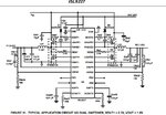
 

Anybody help, please isl6227.JPG
 

I think it extremely unlikely you would get 10V from it, even if you used higher voltage MOSFETS for the output switches and supplied them from > 10V. I think you would need to add an intermediate driver stage to produce enough gate voltage if you did that. The circuit would be inordinately complicated for such a simple task.

Brian.
 

Hi betwixt,
Thanks for your replay, You means the output voltage will affect the selection of MOSFET, isn't it?, the circuit driver the gate through boost diode and capacitor. I want to know why the output should be less than 5.5V, the chip sense the output voltage through Pin Vsen.
 

Two things set the maximum output voltage:

1. the voltage at the top of the upper MOSFET. The output cannot go higher than that even if the MOSFET is fully 'on'.
2. the gate voltage available to turn the MOSFETs on and off. This is generated from inside the ISL6227 and if it isn't high enough the MOSFETS will not be able to switch fully on.

This is why I said you might be able to use the signal coming from the ISL6227 but you would need an extra stage of voltage boosting to make the gate drive signal big enough to fully turn them on and off. There are easier ways to stabilize 10V than to use a regulator designed for low voltage and add extra circuitry to boost it!

Brian.
 
Regaridng basic pwm operation, the transistor voltages are only determined by the converter input voltage, there's no difference between e.g. 5V and 10 V output regarding switcher voltage levels, just a different voltage level.

It's not explicitely specified in the datasheet, but implicitely Voutx pins are limited to Vcc (as "other" pins in maximum ratings). This means they can't be used for output voltages above 5V and must be grounded, which sets device operation to forced PWM. If you don't need the power saving features, this might be a way to operate the device with higher output voltage.
 
  • Like
Reactions: pover

    V

    Points: 2
    Helpful Answer Positive Rating

    pover

    Points: 2
    Helpful Answer Positive Rating
Thanks, FvM I will layout a board and inform you the result.
 

Status
Not open for further replies.

Part and Inventory Search

Welcome to EDABoard.com

Sponsor

Back
Top