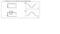
Correct Graphs for the corresponding resonant circuits

Status
Not open for further replies.

santom

Full Member level 2
Joined
Sep 8, 2007
Messages
143
Helped
2
Reputation
4
Reaction score
2
Trophy points
1,298
Activity points
2,255
Hi,
Can anyone tell me which graph suits for which configuration.This is a bit tricky.So think for a while before you start writing your valuable guidelines.

Thanks a lot..


Santom
 

Second graph is for first ckt, first graph for second ckt
 

    santom

    Points: 2
    Helpful Answer Positive Rating
Hi,
Thanks for the reply.But can you please explain that a bit more?

Santom
 

Sure, here it is....

The first figure is a series resonant circuit. At resonance the impedance offered by the L-C combination is j0. Therefore the magnitude of the impedance at resonance is minimum and the current is maximum. If you assume a load resistance across which you measure the Vut, it is maximum.

Similarly, the second diagram is of a parallel resonant circuit, in which, L-C combination shows infinite impedance at resonance, and less impedance at other frequencies. Therefore the current is minimum at resonance. Therefore the output voltage is also minimum at resonance.
 

    santom

    Points: 2
    Helpful Answer Positive Rating
Thanks dude..!
 

Actually, the question does not make sense to me. \[v_{ut}\] in both cases
seems to be an open-circuit voltage. In other words, this is question is ill-posed.
Do you agree? Normally, in this type of a circuit the measured quantity is across
an element. In the circuits that you show, there is no current flowing out of the
ac-source on the left since there is an open-circuit.

If you actually constructed either of these circuits and measured the voltage
\[v_{ut}\], you would simply measure the source voltage and each transfer
function would be flat.

\[v_c\]
 

Status
Not open for further replies.
Cookies are required to use this site. You must accept them to continue using the site. Learn more…