Continue to Site

Welcome to EDAboard.com

Welcome to our site! EDAboard.com is an international Electronics Discussion Forum focused on EDA software, circuits, schematics, books, theory, papers, asic, pld, 8051, DSP, Network, RF, Analog Design, PCB, Service Manuals... and a whole lot more! To participate you need to register. Registration is free. Click here to register now.

[SOLVED] Convert audio to 0-5VDC for ADC by uP

Status
Not open for further replies.

djsfantasi

Advanced Member level 4
Full Member level 1
Joined
Mar 14, 2010
Messages
105
Helped
20
Reputation
40
Reaction score
19
Trophy points
1,308
Location
Boston MA
Activity points
1,931
I am looking for a simple circuit, into which I supply an audio signal, such as from the headphone jack of a PC or CD player. The strength/volume of the signal would then be scaled to 0-5VDC in order to be read by a uP.

The uP is a specialized controller for servos (Lynxmotion SSC-32) and has four built-in analog inputs, with a 5VDC reference voltage. A single byte value is returned, with 0 being 0V and 255 being 4.98V. Unfortunately, the reference voltage cannot be changed, so I want to externally map the audio to this range.

Can anyone help?

Thanks,
dj
[/url]
 

You can employ a rail-to-rail op-amp, supply it of +5V and configure it as AC amplifier with 2.5Vdc offset .. see attached picture ..
The gain [-R3/R2] can be calculated in such a way that the max output signal is within 2.5Vdc - +/-2.5V range ..
Here is an example of low-voltage rail-to-rail opamp:
https://www.analog.com/static/imported-files/data_sheets/AD8691_8692_8694.pdf
google for more ..

Rgds,
IanP
 

This is good information, but I now realize that my question was wrong.

Consider the following diagram:


The graphic to the left represents an audio signal; the black box to the right represents the desired circuit.

At various times, the level of the audio signal determines the voltage on the Output line.

For example, at the following times, the Output is:
== ===
t0 3v
t1 0v
t2 5v
t3 2v

Is this any clearer? The original reply did answer my question; I just had asked the wrong question.
 

This function can be performed by an amplitude detector .. see attached picture ..
To make it working in the 0-5V range you'll have to employ rail-to-rail opamps ..
The detection time constant will depend on R5-C2, you can change to other values if needed ..
Rgds,
IanP
:D
 

    djsfantasi

    Points: 2
    Helpful Answer Positive Rating
Thanks Ian... After continuing to investigate, I have come back to your reply and better understand what you were saying, so this has been an excellent educational opportunity for an electronics novice.

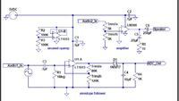
I have come up with the attached circuit and modelled it in LT SPICE and it seems to do what I wish. It is basically your circuit with an envelope follower on the output. I found the envelope follower circuit with a bit of Googling and experimented with SPICE to determine the component values.


Thanks for your help,
dj
 

Many months later, I thought I would report on the progress. I was able to combine the op-amp circuit to shift the voltage range to 0-4.98 V and subsequently use the envelope follower circuit to create a DC signal out that follows the audio waveform approximately. The final circuit, including an audio amplifer, is shown below:


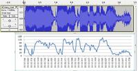
I finally was able to perform a test recently. Here is a picture comparing an audio input to the digital results returned by the A/D converter on my controller board (a Lynxmotion SSC-32 for controlling servos). Note the scale of the two graphs are slightly different, but you can see a correlation between the two signals:


With some software filtering, this will satisfy my needs! (It is to be used to control a servo based on the audio being played)
 
Last edited:

LOL

This is my answer to Scary Terry's audio-servo circuit. I could've used his circuit, but wanted to develop my own for educational purposes. His circuit always drives the servo to the max position; the output of my circuit runs through an embedded A/D converter on a microprocessor and by software control, moves a servo to various positions. His circuit inspired me!
 

Status
Not open for further replies.

Part and Inventory Search

Welcome to EDABoard.com

Sponsor

Back
Top