Continue to Site

Welcome to EDAboard.com

Welcome to our site! EDAboard.com is an international Electronics Discussion Forum focused on EDA software, circuits, schematics, books, theory, papers, asic, pld, 8051, DSP, Network, RF, Analog Design, PCB, Service Manuals... and a whole lot more! To participate you need to register. Registration is free. Click here to register now.

controlling security zone with 2 VDC

Status
Not open for further replies.

deano797

Newbie level 4
Newbie level 4
Joined
Nov 4, 2012
Messages
5
Helped
0
Reputation
0
Reaction score
0
Trophy points
1,281
Activity points
1,323
I am strictly an amateur when it comes to electronics, although I can put together a circuit if I get a schematic. What I am trying to do is trip a 12 VDC relay when the signal is only 2VDC. I assume the 2 VDC would have to control a solid state circuit, which then would control the relay. I want to use the 2 VDC from an indicator LED in a backup generator to control the relay which would be a zone in a security system in a vacation home that is unoccupied for months at a time. I want to be able to detect a generator failure via the security system. I tried to control a 3 VDC relay directly from the LED voltage, but it wouldn't work. Any ideas for a novice? Thanks very much.
 

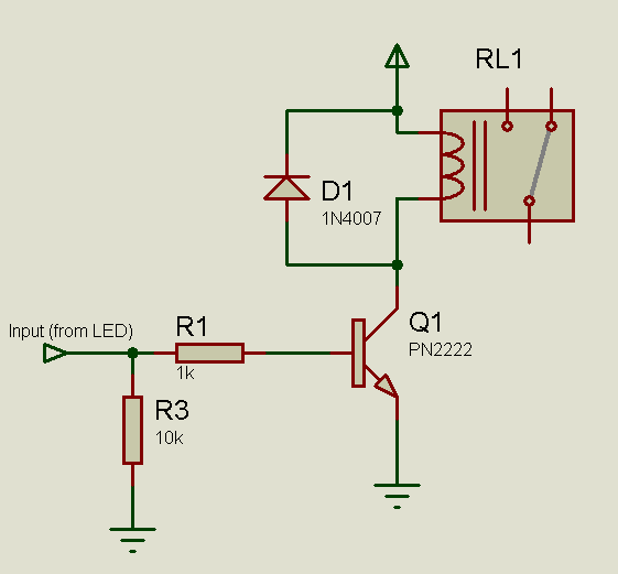
Instead of directly driving the relay, you need to "boost" the current, since the relay will require a much larger current (usually) than can be provided by the current-limiting resistor in series with the LED. A simple transistor driver should solve the problem.

You can use something like this:
4849439700_1352012349.png


Hope this helps.
Tahmid.

Thank you, Tahmid. The relay will either be a miniature dpdt drawing only 60 ma, or a reed (st) which has a coil resistance of 1050 ohms and therefor needs only 15 ma. I could also use a 5VDC reed, with a coil R of 250 ohms. Would the Power to the LED at 2VDC be enough, after going thru your design, be strong enough and be at either 12VDC or 5VDC? I don't need any other source of power? I assume the LED would have the same common ground with the circuit you designed. Correct? The security zone circuit draws very little power. It just needs to detect a change in resistance. Thanks again deano797

- - - Updated - - -

Thank you, Tahmid. The relay will either be a miniature dpdt drawing only 60 ma, or a reed (st) which has a coil resistance of 1050 ohms and therefor needs only 15 ma. I could also use a 5VDC reed, with a coil R of 250 ohms. Would the Power to the LED at 2VDC be enough, after going thru your design, be strong enough and be at either 12VDC or 5VDC? I don't need any other source of power? I assume the LED would have the same common ground with the circuit you designed. Correct? The security zone circuit draws very little power. It just needs to detect a change in resistance. Thanks again deano797
 

Being the amateur that I am, I finally figured out that the relay would be receiving 12VDC, regulated by the transistor with the 2VDC base current from the LED.
 

The 2V you receive from the LED has limited current capacity (if you don't want to disrupt the LED, assume it is near zero and that all current is going through LED). However there is enough current (and obviously sufficient voltage) to turn on the high gain NPN transistor, which can then drive the relay that should be running off a different power supply (different voltage, higher current capacity, same ground).

It doesn't necessarily have to be 12V. If you're using a 5V relay, you can use 5V. If you're using a 9V relay, you can use 9V. And so on.

Hope this helps.
Tahmid.
 
Thanks Tahmid, from Madison, Wisconsin. I will build the circuit and let you know if it works o.k.
 

Use optocoupler to sense LED current and on other side where is photo transistor power relay or what you want with adequate voltage and current. You can put optocoupler LED side in serie with existing red led.

I tried to control a 3 VDC relay directly from the LED voltage, but it wouldn't work.

You say LED have 2V, and its probably RED, and I guess its low current, that means 2mA of current, that is to small amount of current even for that tiny relay.

Or of course you can do this as Tahmid suggest.
 
Last edited:

I built the circuit, Tahmid, and it works fine using a 1.5 alkaline battery as a trigger source, I assume the 2 VDC from the LED in the generator ( that's what I want to monitor remotely) will also open current through the PN2222 and relay. Thanks a lot!! One question: why the 10K resistor to ground on the trigger source? Deano798
 
Last edited:

Status
Not open for further replies.

Part and Inventory Search

Welcome to EDABoard.com

Sponsor

Back
Top