Continue to Site

Welcome to EDAboard.com

Welcome to our site! EDAboard.com is an international Electronics Discussion Forum focused on EDA software, circuits, schematics, books, theory, papers, asic, pld, 8051, DSP, Network, RF, Analog Design, PCB, Service Manuals... and a whole lot more! To participate you need to register. Registration is free. Click here to register now.

[SOLVED] Controlling miltiple power led drivers

Status
Not open for further replies.

jelezarov

Member level 1
Member level 1
Joined
Jan 29, 2016
Messages
32
Helped
0
Reputation
0
Reaction score
0
Trophy points
6
Activity points
313
Hi,

I have a couple of power-LED's, which I intent to control with an Arduino (not directly, with transistors), to achieve chase lights or other patterns. After trying different resistors, I gave up because of the heat problems. I found following circuit in an ON Semiconductor application brief:

led_driver.png

Now, where should the controlling transistor go - in series with the LED, or turning the complete driver on/off?

Other suggestions are of course most welcome.
 

Consider the AVR microcontroller high total current level limits through its outputs, 40mA max per pin, 200mA max overall.

Which is the current you intend to supply to the LEDs? Perhaps a Power LED Driver plus your transistors could be an easier solution for your design.
 

Attachments

  • ATMega Max Current.png
    ATMega Max Current.png
    38 KB · Views: 201
Last edited:

Your schematic is for an LED driver utilizing the current limiting facility in the MC34063 regulator, it isn't an LED driver as such, it is a general purpose power supply but wired to drive an LED. It does not have a shut down control and adding one would involve adding extra components that would make it far more complicated than a normal LED driver.

If all you want to do is make a light chaser, just use the Arduino pins to drive a single NPN transistor through a base resistor (about 470 Ohms). Connect the emitter to ground and put an LED and series current limiting resistor in the collector. The series resistor value should be (supply voltage - LED forward voltage)/LED current. So for example if you wanted the LED to pass 50mA and it had a Vf of 2V and you supply was 5V, the resistor would be (5-2)/0.05 = 60 Ohms. Just repeat the circuit for each LED and Arduino pin.

Brian.
 

Thanks to both of you @hyprfrcx and @betwixt for your answers. I suppose my question was not well formulated. I'll try to be more precise:

I have 9 LED's, which consume about ~260mA current each. The Arduino switches them on and off over 2n2222 transistors with 200 Ohm resistors between the base and Arduino.

The supply is 12Volt /4.2A. With 27 Ohm resistors in series with the LED's everything works fine, except the heat.

Therefore I wanted to try something more efficient. As a hobbyist of course trying to find the balance of between simple and effective.

I do not have a datasheet, just tried different resistances and measured. It is an old signaling lamp, but the LED's are still working and wanted to make something of it.
 

Hi,

A question I have is the following: Are you driving the LEDS/the 2N2222s via the Arduino with a signal like a or a signal like b?

led driver thread pd.jpg

I guess/hope you mean like b due to the huge reduction in heat and savings in unnecessary power use (260mA/4 = 65mA average over time, or e.g. 3V * 65mA = 195mW/LED as opposed to 780mW/LED...2N2222s - I doubt they want to endure 780mW as they are more like roughly 600mW max., from memory) and as we know, slow human eyes/POV is important to consider...

So what's your driving signal like, then, please?
 
Out of curiosity just connected one LED to a 5V power supply, over a 2.2 Ohm resistor. Everything runs cold, current is ~0.22A and the voltage drop over the LED is ~4.5V. Could there be any problem with this approach? I have a bad feeling that there is a reason for all this complicated circuits to exist...

- - - Updated - - -

Hi,

A question I have is the following: Are you driving the LEDS/the 2N2222s via the Arduino with a signal like a or a signal like b?

View attachment 152943

I guess/hope you mean like b due to the huge reduction in heat and savings in unnecessary power use (260mA/4 = 65mA average over time, or e.g. 3V * 65mA = 195mW/LED as opposed to 780mW/LED...2N2222s - I doubt they want to endure 780mW as they are more like roughly 600mW max., from memory) and as we know, slow human eyes/POV is important to consider...

So what's your driving signal like, then, please?

a) :/
I never considered such thing, but sounds great. I will try to improve in this direction too.
 
Last edited:

Hi,

Oops, my mistake, it's unlikely your 2N2222s will have 3V * 260mA across them, more likely a few hundred mV at most, so not to worry, you say 0.5V * 0.22A = 110mW, definitely all is fine there. Presumably your LEDs have a Vf of 4.5V.

There's no problem with your approach, so long as everything is operated within its recommended - not maximum - operating conditions, which it seems they are.

You do read datasheets, don't you? Sorry to ask but it's a just-in-case question. Circuits, IMO, start with an idea, then become a schematic, then comes the maths to see it can all work safely, etc. Beginners' delight and beginners' mistake (I did it too at first) is just connecting components to electricity and expecting everything to work like a light switch without having even looked at a datasheet.

If you can code a pulse like signal b with your Arduino, you'll save e.g. 75% of the energy signal a would use. It's easy to create both in analog and digital. Give it a go, think of the planet and your electricity/battery bills and all that stuff.
 

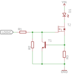
In case anyone else is having the same problem like me, here is how I solved it:

LED_driver.png

The "logic" input comes from the Arduino (actually in my case from a shift register). T1 is the humble 2n2222, T2 is IRL3705N - or any other N-Channel power MOSFET with logic level gate, R1 is 10k, R2 - 100k. R3 sets the current like this:

R = 0.6/If

For my case I wanted 250mA, so R3 = 2.4Ohm.
Using 7V 5A power supply and everything works fine. More voltage on the power supply would mean more heat in the MOSFET.
 

Out of curiosity just connected one LED to a 5V power supply, over a 2.2 Ohm resistor. Everything runs cold, current is ~0.22A and the voltage drop over the LED is ~4.5V. Could there be any problem with this approach? I have a bad feeling that there is a reason for all this complicated circuits to exist

and there in lies your answer. For whatever reason your LEDS are 4.5v/0.25A devices. Simply power them from a 5v switcher with maybe 1-2 ohm in series.

- - - Updated - - -

Total resistor power ~1.1w across 9 resistors.
 

Status
Not open for further replies.

Similar threads

Part and Inventory Search

Welcome to EDABoard.com

Sponsor

Back
Top