Continue to Site

Welcome to EDAboard.com

Welcome to our site! EDAboard.com is an international Electronics Discussion Forum focused on EDA software, circuits, schematics, books, theory, papers, asic, pld, 8051, DSP, Network, RF, Analog Design, PCB, Service Manuals... and a whole lot more! To participate you need to register. Registration is free. Click here to register now.

Controlling an AC Motor by PIC16F84A

Status
Not open for further replies.

Green_Peace09

Newbie level 3
Newbie level 3
Joined
Mar 15, 2007
Messages
4
Helped
0
Reputation
0
Reaction score
0
Trophy points
1,281
Activity points
1,313
Hi Everybody,

I have a problem that I could not solve. For a project, I am controlling an 180 watts and 220 Volts AC motor by Using a PIC16F84A. But I also want to stop the motor when it is overloaded, without using a fuse. For example, when the motor is overloaded, there will be much current flow in the circuit. How can I sense this much current, transmit this data to the PIC ? Could you please help me for this ?

Kind regards.
 

What about rpm's ?

Will the rpm's be affected by the overload ?

Can you measure the rpm's using a optical sensor ?

if you can do it, just conect a photosensor similar to the ones on the computer mouse and count the rpm's (digital pulses), and based on this you can decide to stop the motor or not
 
there are many ways.. in a nut shell, you must sense the current, compare it to a threshold voltage and then turn OFF the motor by disabling the output (motor coasts to a stop).

i'll assume your topology is a single phase full H-bridge, very common for your power level and application. you can put a current sensor in series with each wire going to your motor (phase over-current detection) or you can put a sense resistor. a sense resistor is probably cheap, but if you're just building one i'd go with the full open-loop current sensor beacuse you can get free samples from Alegro.

also make sure you isolate the signal before it gets to your microprocessor. a current sensor has this built in, but a sense resistor + diff. amplifier method does not (usually).

good luck,
Mr.Cool
 
Dear Friends,

Thanks alot for your valuable answers, they are very useful.

And by the way, yes, I can count the rpm by using a kind of photosensor. But in my sysstem this would not be very effective. I am triying to make a cow brush for my friend's cows and using a photosensor (or another device like reed relay) is very hard, because the animals always swings this brush very much and this situations hams the precision of the sensor. So, I have to control the on/off process by measuring (or sensing) the current. Could you please advice me another alternative method.

Kind regards and thanks.
 

Brother I believe if you upload the schematic you have made will let users easily identify the problem.
 
Dear Friends,

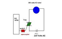
Thank you all for your help. Attached is the very simple schematic of the system. According to this schematic, could you please give me more advice about my problem.

Kind regards.


If your over load current is high,u've got to put high wattage resistors.there are chances that these resistors may get overheated and gets derrated...another option is to use a current transformer,which doesnt create such problems..
 
Dear Friends,

Thank you all for your helps. all of them are useful.

Regards.
 

really sorry to hack the thread but i think its stoped since a long time

well i want to know that can i use shunt resistor in ac.. if yes wont there be problem with using comparator to compare voltages across a ac circuit ?
 

Status
Not open for further replies.

Part and Inventory Search

Welcome to EDABoard.com

Sponsor

Back
Top