gres
Full Member level 4


It's a two 5mm perspex stars with inscription.
Pattern is made in autocad. Print out glued to perspex and cut by multi grinder with corundum disk. When you are cuting, drilling or grinding perspex you have to obey two rules : slow and smooth. Cut with light pressure, with often brakes for cooling surface. Inscription is made with help of pattern print in mirror mode put from bottom side.
I made backlight, based on project RGB lamp from
"driver" of RGB diodes with common anode.
Diagram looks like this

Now i explain why i put transistors to only one diode. Of course you can connect diode directly to microcontroller port, but i'm thinning about add a few more diodes. I also thinning about making perspex "glass bombs" with motifs. So we can say that drivers has some reserves. Before connect more diodes we had to exchanged R4 R5 and R6 into thier equivalent but with power 0.5-1W. giving 20mA current per RGB diode segment, on stabilizer and transistors ( collector current 800mA) to driver you can connect about 16 diodes. That limit can be rise by changing stabilizer on to element with bigger load carrying capacity - up to 40 diodes in theory ( 40 x 20 mA=800mA).
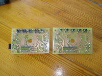
At https://www.elektroda.pl/rtvforum/topic1517618.html you can find board diagrams, panel description ...).
Board is such design that after had solder, switches from print side and connected it in the casing ( paths up) they are situated in right sequence (S1-S5).

