Continue to Site

Welcome to EDAboard.com

Welcome to our site! EDAboard.com is an international Electronics Discussion Forum focused on EDA software, circuits, schematics, books, theory, papers, asic, pld, 8051, DSP, Network, RF, Analog Design, PCB, Service Manuals... and a whole lot more! To participate you need to register. Registration is free. Click here to register now.

Control a current limiting pin

Nucrino

Newbie level 4
Newbie level 4
Joined
Feb 22, 2024
Messages
7
Helped
0
Reputation
0
Reaction score
0
Trophy points
1
Activity points
73
Hello
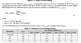
I am trying to find a solution to control the REF pin of the TPS929160-Q1. The datasheets explains that the output current can be set with the Rref resistance, and I would like to know if anyone would have an idea to control this pin and by doing so control the output current ?

Would it be possible to put a voltage controlled current source there and by doing so create a Iref proportional to the voltage input ?
My requirements :

I cannot use a potentiometer, controling this pin with a voltage is basically my only option for this project.
I know that you can program the output current but i need it to be analog.

Thanks for your help !
Component Datasheet

Capture6.PNG
 
Solution
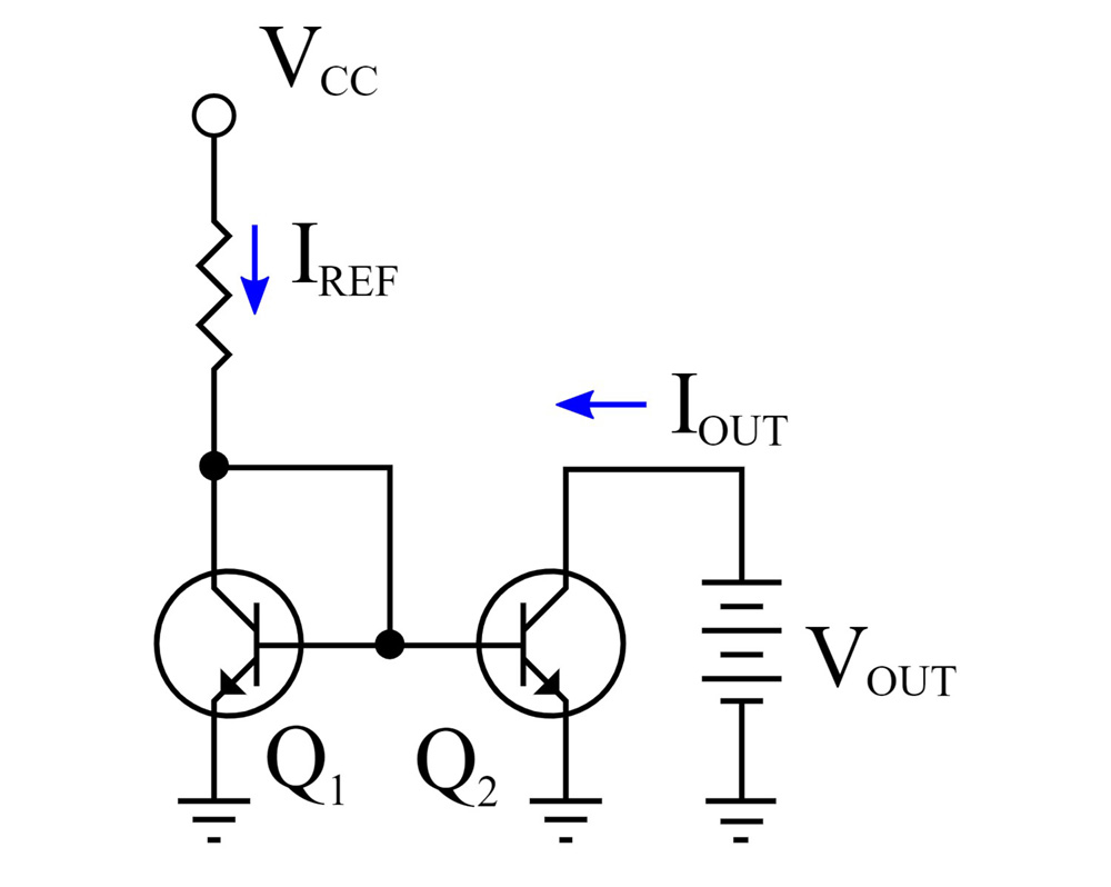
Below is the LTspice sim of a current-mirror circuit as Tony suggested, which would seem to be the simplest solution:
The values shown give a 0-200µA max current (yellow trace) from the Ref pin for a 0-5V Cntl input (green trace).
The max current is based upon the lowest value of resistor (1.235V / 6.34KΩ) given in Table 7.1.

The current range is controlled by the input voltage and the value of R1 below.
For example R1=11.5kΩ would give the same 0-200µA range for a 0-3V input.

1708632669794.png
I would start with a current mirror as the voltage is fixed and current range limited. with voltage-controlled current with a matched pair package or similar.


1708622217559.png
1708622384555.png
 
Hi,

it´s not clear what you want to achieve.

What does "control a pin" mean?
The voltage at this pin should be constant.
Maybe you want to control the current at the REF pin. --> then simply change the resistance of R_REF.

The datasheets explains that the output current can be set with the Rref resistance
R_Ref is connected to REF_pin. Change of R_Ref will change the current at the REF_pin.
...and further this will set the range of the output current of OUTAx pins.

Would it be possible to put a voltage controlled current source there and by doing so create a Iref proportional to the voltage input ?
For sure you may use a current source ... as long as you are within the datasheet given limits.

***
I´m still unsure if this is what you want.
Then you get something that is called a "multiplying DAC".

***
Requirements should come with values. We don´t know your analog_voltage range, the expected REF_pin current range, the frequency bandwidth....

Klaus
 
Below is the LTspice sim of a current-mirror circuit as Tony suggested, which would seem to be the simplest solution:
The values shown give a 0-200µA max current (yellow trace) from the Ref pin for a 0-5V Cntl input (green trace).
The max current is based upon the lowest value of resistor (1.235V / 6.34KΩ) given in Table 7.1.

The current range is controlled by the input voltage and the value of R1 below.
For example R1=11.5kΩ would give the same 0-200µA range for a 0-3V input.

1708632669794.png
 
Last edited:
Solution
Hi,

it´s not clear what you want to achieve.

What does "control a pin" mean?
The voltage at this pin should be constant.
Maybe you want to control the current at the REF pin. --> then simply change the resistance of R_REF.


R_Ref is connected to REF_pin. Change of R_Ref will change the current at the REF_pin.
...and further this will set the range of the output current of OUTAx pins.


For sure you may use a current source ... as long as you are within the datasheet given limits.

***
I´m still unsure if this is what you want.
Then you get something that is called a "multiplying DAC".

***
Requirements should come with values. We don´t know your analog_voltage range, the expected REF_pin current range, the frequency bandwidth....

Klaus
Hi, first of all thank you for your answer.
Yes, when I said "control the pin" I meant control the current to the REF pin.
What i am trying to do is to set the current output with an analog signal, so changing the resistance is a no go.
As for my recquirements :
- the analog signal vary from 0V to 28V.
- the LEDs I intend to drive have a If of 35 mA maximum, so I would need to vary Iout from 0 to 35 mA. The datasheet shows the graph below, it seems doable to at least make it range from 8mA to 35mA.
Capture8.PNG

From what I understood, the output current is equal to Iref * K, K being programmable (default value is 512) . So using a Voltage controlled current source, I would just need to send a current equal to Iout_wanted/K no ?
Hope i gave you enough informations, if not do not hesitate.
Thanks
 
Below is the LTspice sim of a current-mirror circuit as Tony suggested, which would seem to be the simplest solution:
The values shown give a 0-200µA max current (yellow trace) from the Ref pin for a 0-5V Cntl input (green trace).
The max current is based upon the lowest value of resistor (1.235V / 6.34KΩ) given in Table 7.1.

The current range is controlled by the input voltage and the value of R1 below.
For example R1=11.5kΩ would give the same 0-200µA range for a 0-3V input.

View attachment 188912
Thanks for your answer
As I said in my answer to Klaus, my analog signal has a 0-28V range, and I would need my output current to range from at least 8mA to 35mA
Now, if my pre-programmed K is equal to 512, then i would need a maximum of 70µA to achieve 35mA in the output (assuming my calculations are correct :) )
So your solution would work, as for the range of the analog signal, maybe I could use a voltage divider to have my analog signal range from 0 to 2.8V ? (divide by 10)
Thank you !
 
A digital potentiometer will work.
https://www.analog.com/media/en/new...ection-guide/Choosing_the_Correct_Digipot.pdf

I you are only interested in changing between a few numbers of predefined amplitudes, you might simply connect different resistors (in parallel) between thr REF pin and ground via transistors. N transistor, N resistors and N GPIO pins, allow 2^N different settings.

a digital potentiometer or a digital controlled resistor bank will not be suitable for you :/
No worries I explained my problem extremely bad.
As for the Transistors, i have been looking in that direction, but I would need to create a lot of parallel branches to make it work the way I intend to.
 
Hi,

Yes, I think a voltage controlled current source (or better say "current sink") is the way to go.

I´d divide the 0..28V down to let´s say 0..0.6V or so (half of the 1.23V to leave enough headroom) using two resistors.
then use a MOSFET with Shunt (0.6V / 70uA = 8.5kOhms)
Then use an OPAMP as regualtor: IN+ = input from voltage divider, IN- is feedback from shunt.
(eventually add some RC for stability improvement)

Schematics are all over the internet.

Klaus
 
my analog signal has a 0-28V range
Now, if my pre-programmed K is equal to 512, then i would need a maximum of 70µA to achieve 35mA in the output (assuming my calculations are correct
That looks correct.
Below is the current-mirror circuit to give that current from 28V in:

The Ref output mirror-current is basically (Vcntl - 0.6V) / R1.

1708711413299.png
 

LaTeX Commands Quick-Menu:

Part and Inventory Search

Welcome to EDABoard.com

Sponsor

Back
Top