Continue to Site

Continuous output current (solar charger)

riscv

Newbie level 6
Newbie level 6
Joined
Mar 24, 2025
Messages
12
Helped
0
Reputation
0
Reaction score
0
Trophy points
1
Activity points
80
Hi,

I'm trying to design a solar battery charger using this simplified buck-boost topology:

chg.gif


However, I do prefer a continuous output current (for a reason) and I was thinking of inserting a second output inductor like this:

chg1.gif


But I don't know how to estimate the voltage at the point marked in red, because in this case that voltage seems to be floating (no longer being "stabilized" by the battery). And this has a direct influence on the voltage ratings of both the high side mosfet and the schottky diode. Is there any other way to smooth the output current? Should I use a big(ger) output capacitor instead?
 
Last edited:
Any insight on this matter? I'm trying to run a simulation (ngspice/KiCad) but I run into some undocumented errors.
 
To make this work you need design specs. Otherwise if you do not match the impedance of the PV with your DCDC converter, your efficiency will fail miserably.

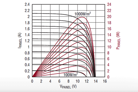
We know that in full sun = 100 kLux typ. 1kW/m2 that the you will be very close to the Maximum Power Point (MPP) using 82% of the no load voltage= Voc regardless of the PV size. If you want a simple design useful down to 10% of this maximum solarity with out a more complex MPPT controller, I can guide you to create your own design specs.

1. Get some 5mm Vishay photodiodes (PD) and a diffusion material (e.g.mylar) to create a large aperture that the PD average to measure solarity with a Ir*R=Vr using an Op Amp buffer. This can make an inexpensive solar power meter which you can calibrate. But you will use that to regulate the load conductance of your current charger. Although power rises with square of voltage or current into a fixed resistance, a diode is not a fixed resistance. If you examine multiple solarity MPPT curves you will see a linear rise in power with load voltage up to the peak power point Pmpt = 82% Voc and see your Pmpt decline to 10% max power at low solarity while the voltage is only 33V/48V = 69% of Voc max. (estimate) This means Vpv is a linear function of power and you will use these PD sensors to measure a ratio of that voltage. This will depend on matching the beamwidth sensitivities of the PD to the flat PV array by experiement. I would compare wide angle PD's with narrow beam PD aimed under the diffuse translucent thinfilm panel of plastic like Mylar. You may find wet/dry sanding of a <=30 deg lens does the same. Both will lose calibration due to dust, dirt so cleaning is necessary.

2. Now how do you regulate the PV's Vmpt voltage and the battery V/I current according to its CC/CV/cutoff protocol independent of each other. You must use start with a linear boost regulator like an active PFC circuit then use multiple feedback circuits to regulate the PV input current and voltage before and after sunrise and regulate according the PD voltage and load demand. Understand? Now go get some equpment to conduct some solarity tests to confirm my assertions are valid for your PV and compare with a solarity meter you buy or make.
--- Updated ---


This is what 29s of "smart enhanced" AI says about the above (Grok3)....

To simplify the process of designing an efficient battery charger using a photovoltaic (PV) panel, you need to focus on making the system work well with the solar panel’s output. Without proper design specifications, the efficiency can drop significantly because the PV panel and the DC-DC converter won’t work together effectively. Here’s a straightforward explanation and guide based on the ideas provided:

Why Design Specs Matter
For a solar panel to charge a battery efficiently, it needs to operate at its Maximum Power Point (MPP)—the spot where it produces the most power. This depends on matching the panel’s impedance (its resistance to electrical flow) with the DC-DC converter. If these don’t align, you lose a lot of energy, and the system performs poorly.

Key Insight: Operating at 82% of Open-Circuit Voltage (Voc) ( in full sun)
In full sunlight (about 100 kLux or 1 kW/m²), the MPP is typically at 82% of the panel’s open-circuit voltage (Voc)—the voltage when no load is connected. This is a handy rule of thumb because it works for most PV panels, regardless of size. For a simple design that still works when sunlight drops to 10% of its maximum (low solarity), you can avoid complex Maximum Power Point Tracking (MPPT) controllers by regulating the system to stay near this 82% mark.

Simplified Design Approach
Here’s how to create a basic, efficient system without overcomplicating things:
1. Measure Sunlight with Photodiodes

  • What you need: Get some 5mm Vishay photodiodes (PDs) and a diffusion material like Mylar (a thin plastic film).
  • How it works: The photodiodes sense light intensity (solarity). Cover them with the diffusion material to average out the light over a wider area, mimicking what the PV panel sees. Connect the photodiode to a simple circuit (like an Op Amp buffer) to convert its current into a voltage (Vr = Ir × R). This gives you a cheap solar power meter.
  • Purpose: Use this voltage to estimate how much sunlight is hitting the panel and adjust the system accordingly.
2. Adjust the PV Panel’s Operating Point
  • Goal: Keep the PV panel’s voltage (Vpv) close to the MPP, which is around 82% of Voc in full sun.
  • Why it’s tricky: The panel’s power output changes with sunlight, and its behavior isn’t like a fixed resistor—it’s a diode with a curved voltage-power relationship. In bright light, power increases as voltage rises up to the MPP, then drops off. In low light (10% solarity), the MPP voltage might fall to around 69% of the maximum Voc, but power drops much more (to less than 10% of max).
  • Solution: Use the photodiode’s voltage to figure out the sunlight level and tweak the DC-DC converter to set the PV voltage near the MPP. You’ll need to experiment with the photodiodes’ sensitivity (their “beamwidth”) to match the PV panel’s response—try wide-angle photodiodes or narrow ones with diffusion (e.g., sanded plastic or Mylar).
3. Charge the Battery Properly
  • Battery charging stages: Batteries charge in phases—Constant Current (CC) to fill them up, Constant Voltage (CV) to top them off, and cutoff when they’re full.
  • How to do it: Use a linear boost regulator (similar to a Power Factor Correction circuit) as your DC-DC converter. Add feedback circuits to:
    • Control the PV panel’s input voltage and current based on the photodiode reading.
    • Adjust the output to the battery based on its charging needs (CC, CV, or cutoff).
  • Key: The PV regulation (for MPP) and battery charging (CC/CV) should work independently but together, adapting to sunlight and battery state.
Putting It All Together
Here’s the simple version of the system:

  1. Measure sunlight: Photodiodes with diffusion give you a voltage proportional to light intensity.
  2. Set the PV voltage: Use that voltage to adjust the DC-DC converter so the PV panel runs near its MPP (e.g., 82% of Voc in full sun, adjusted for lower light).
  3. Charge the battery: The converter boosts the PV output and follows the CC/CV/cutoff protocol to charge the battery safely and efficiently.
Tips for Success
  • Test it out: Grab your PV panel, photodiodes, and some basic electronics to run solarity tests. Compare your photodiode readings with a real solar meter (bought or homemade) to calibrate everything.
  • Keep it clean: Dust or dirt on the photodiodes or PV panel will throw off your measurements, so clean them regularly.
  • Experiment: Play with different photodiode setups (wide-angle vs. diffused narrow-beam) to see what matches your PV panel best.
In Simple Terms
To charge a battery efficiently with a solar panel, make sure the panel works at its best power point. Use light sensors (photodiodes) to measure sunlight and adjust the system to keep the panel’s voltage near that sweet spot (like 82% of Voc). Then, control the battery charging so it fills up properly without overdoing it. With some basic parts and testing, you can build a simple, effective charger that works even when the sun isn’t at full strength.


My post comments
Close to 82% is not the overall goal unless the sun directly overhead pointing at your array with a clear sky. That's why the PD sensors are used. You need 3 if you want to control the panel angle and a smart energy servo to know when the gain is more than the loss. Of course you can also pulse your PV open circuit if you prefer to get Voc reference voltage but that's the simple job of the PD sensors to measure no load solar current.

View attachment 198526
--- Updated ---

 
Last edited:

    riscv

    Points: 2
    Helpful Answer Positive Rating
The PV solar array is largely oversized, the only focus is on the battery charging process (the MPPT is almost out of question).

I only monitor the battery charging current and its voltage, and do a basic P&O algorithm on cloudy days.

I prefer a continuous charging current because the current sensor readings will be more accurate (otherwise I need a lot of sampling, to get precise monitoring of the battery in/out energy).
 
I prefer to keep the discussion on topic, many thanks for your insights.

I just want to know if there's a way to get continuous output current using an extra output inductor.
 
Define your safety limits , Rth, Vmax, Irms and target efficiency losses, budget, time and goals (outcome)

Rather than try to reinvent the wheel, use the best topology. examine WPT & EV technology research comparisons.

SEPIC converters use dual coils but are very challenging due to the coupling capacitor RMS current or power transfer limits and costs.
 
So basically you want a buckboost type thing to go from solar to batt with output currnt control(?)

Easy cheap way is to just use uncoupled SEPIC and regulate the output currnt.
You know how to regulate output currnt?
(if not i show you in LTspice sim?)
SEPIC no high side fet drive
SEPIC no high side currnt sense.
This is why i say SEPIC.
incidentally what kwh is the battery?
How many solar panels and of what power they are?

On the other hand........
If you dont need the solarBattery to be grounded to system ground, then why not do a BuckBoost_with_load_referred_to_vin?
This is a very simple buckboost with simple low side fet and low side currnt sense, but the load is referenced to vin.
This could be a nice simple way for you. Add in the solarBattery current regulation and you're done.
 
Last edited:
And if SEPIC done with a coupled inductor, then the RMS current in the coupling capacitor is very much lower. But can you be bothered with a coupled inductor?


Write your reply...

LaTeX Commands Quick-Menu:

Similar threads

Part and Inventory Search

Welcome to EDABoard.com

Sponsor

Back
Top