Continue to Site

Welcome to EDAboard.com

Welcome to our site! EDAboard.com is an international Electronics Discussion Forum focused on EDA software, circuits, schematics, books, theory, papers, asic, pld, 8051, DSP, Network, RF, Analog Design, PCB, Service Manuals... and a whole lot more! To participate you need to register. Registration is free. Click here to register now.

Constant current LED Driver Circuit

gauravkothari23

Advanced Member level 2
Joined
Mar 21, 2015
Messages
642
Helped
5
Reputation
10
Reaction score
4
Trophy points
1,298
Activity points
6,934
Hi All.
I Am using a Constant current circuit (Attached) to drive the SMD LED's.
i am using Approx 750mA of Current to drive a LED's with 5V input which is working fine. Mosfet used is SMD SOT23 Package AO3400. My problem is the mosfet gets extremely hot around 70 to 75 degree Celsius within 10 to 12 seconds.
Can anybody please suggest me why the mosfet is getting hot and how can i avoid it. What changes are required to be done in my existing circuit.
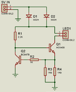
 

Attachments

  • CC Circuit.png
    CC Circuit.png
    20.2 KB · Views: 742
AO3400 is an NFET not NPN

You need to apply thermodynamics.

Rja = 125'C/W . Likely you need a large Cu PCB heatsink or use a TO-220 2 sqin/W min of Cu.

5V?
5V * 750 mA = 3.75 W

Where is your thermal design and power budget?
 
Last edited:
AO3400 is an NFET not NPN

You need to apply thermodynamics.

Rja = 125'C/W . Likely you need a large Cu PCB heatsink or use a TO-220 2 sqin/W min of Cu.

5V?
5V * 750 mA = 3.75 W

Where is your thermal design and power budget?
For selecting this Mosfet AO3400, i considered the RDSon as it it quite low (33mohms)
because Using 220 Package was not possible because of the limitation of space in PCB.
 
You are not using the "FET" where it delivers low Rds(on). You
are using it as a dissipative element. You'd be as well off with
a NPN as shown (maybe better off, re ruggedness).

Everybody but everybody drives LEDs PWM or PFM style with
switched FETs, which are used as they are meant to be.

If you insist to use a linear sink drive I would recommend an
old timey power bipolar transistor with a good case and low
thetaJC. It will get just as hot with no heat sink and still air but
you would have something meant for the abuse and cheap.

I'm pretty sure there's no shortage of cheap little LED driver
DC-DC boards. If you chased down LED driver ICs and looked
at their application notes, there's probably an eval board BOM
and schematic which could be educational.
 
Hi,

basically you are using a linear circuit.

And knowing this ... it also means that the power dissipation always is (bigger than):

P_tot = (V_in - V_Led) * I_Led.

It does not matter how you do it: Via MOSFET, via BJT, via resistor ... or whatever you decide to use. .. it´s always the same!

So to reduce the dissipated heat you only have these options:
* reduce V_in
* increase V_Led (maybe by using two or more in series)
* reduce the LED current
* .... or use switch mode circuit instead of linear circuit

Klaus
 
i considered the RDSon as it it quite low (33mohms)
Just do a simple test and measure the voltage accros DS of the MOSFET.
According your idea it should be 0.75A x 0.033 Ohms = 0.025V

But I expect about 1V .... this is 40 times higher than you expect.

****
Btw: I see you paralleled to diodes.
You should read about the problem of parlleling diodes.
Do a thermal test: in most cases one diode becomes hot (in your case warm), while the other (usless one) stays cold.
It does neither reduce forward voltage nor power dissipation in an effective way.

Klaus
 
1708245857550.png


Using your FET if it works at logic levels and any NPN like PN2222A , Silicon Diode or any >=1A diode

Quick N Dirty pulsed driver with DImmjer R.. Dne during watching a movie, so not optimal.

Tell me what you understand in this design. Gate capacitance Ciss is internal was added.
 
View attachment 188782


Using your FET if it works at logic levels and any NPN like PN2222A , Silicon Diode or any >=1A diode

Quick N Dirty pulsed driver with DImmjer R.. Dne during watching a movie, so not optimal.

Tell me what you understand in this design. Gate capacitance Ciss is internal was added.
Sorry Sir,
Have not understood anything. Can you please explain
Hi,

basically you are using a linear circuit.

And knowing this ... it also means that the power dissipation always is (bigger than):

P_tot = (V_in - V_Led) * I_Led.

It does not matter how you do it: Via MOSFET, via BJT, via resistor ... or whatever you decide to use. .. it´s always the same!

So to reduce the dissipated heat you only have these options:
* reduce V_in
* increase V_Led (maybe by using two or more in series)
* reduce the LED current
* .... or use switch mode circuit instead of linear circuit

Klaus
Got your point.
will try the options provided by you.
 
As noted, you need to use a constant-current, switch-mode supply if you want to minimize the power dissipation.

Simply using the transistor as a PWM switch will just remove the dissipation from the transistor to the series LED current-limit resistor for the same average LED current.
 
THat's basically why mine works better. It is based on the classic 2 transistor Astable Multivibrator but it senses peak current to cut OFF the FET and create a lower duty with negative feedback from NPN C-E by reducing that R to make a sawtooth on Vbe and a pulse onto the gate.

If you tie the two diodes together thermally (somehow) , they share temperature-voltage characteristics of -4mV/'C then share current better. Otherwise the better diode gets hotter and starts hogging current with a lower voltage in a condition called "thermal runaway".

Clicking on the blue hyperlink allows you to tweak the values interactively.

If you ask questions, that will tell me what you need to learn.
 
Last edited:
Should not take too much of a heat sink, PCB Cu area, 2W in the MOSFET, T's shown as 20 - 70 C, 5 steps each curve.
But max Pdiss is speced at 1.1W @ Tcase of 70 C, so maybe a better choice is needed for this. Run the thermal numbers
on this for better insight. The part will do 1.7W at Tc = 25 C, so even that is a little light given sim did not look at
R's and complete Schottky as worst case as well.


LED used Red, shorter wavelength colors even less MOSFET Pdiss.

Maybe the thermal tool in Webench.... https://www.ti.com/tool/WEBENCH-CIRCUIT-DESIGNER


1708272990736.png


Regards, Dana.
 
Last edited:
THat's basically why mine works better. It is based on the classic 2 transistor Astable Multivibrator but it senses peak current to cut OFF the FET and create a lower duty with negative feedback from NPN C-E by reducing that R to make a sawtooth on Vbe and a pulse onto the gate.

If you tie the two diodes together thermally (somehow) , they share temperature-voltage characteristics of -4mV/'C then share current better. Otherwise the better diode gets hotter and starts hogging current with a lower voltage in a condition called "thermal runaway".

Clicking on the blue hyperlink allows you to tweak the values interactively.

If you ask questions, that will tell me what you need to learn.
i have gone through the stimulation you sent.
changing the dimmer resistor, also changes the duty cycle. but also will reduce the LED brightness. which i cannot.
 
SO what exactly is your assumption? measurement data? understanding ? and question?

Can you read the average Power on each part plot? The dimmer was not meant to be perfect with a quick design, just adjustable to a safe LED temperature.
 
Last edited:
SO what exactly is your assumption? measurement data? understanding ? and question?

Can you read the average Power on each part plot? The dimmer was not meant to be perfect with a quick design, just adjustable to a safe LED temperature.
As per what i have understood reading the datasheet is Pd is120 degree per watts.
but as per the stimulation you sent, the power consumption of mosfet is approx 116mW when in ON condition. So 120 Degree x 116mW which gives me 13.92 + 25 degree ambient temp which is approx 38.92.
but in actual the temperature is near about 70 degree. this is where it confuses me.
Please correct me, if i am wrong.
 
THat's basically why mine works better.
Better in which regard?
I don´t think it´s better regarding over all power efficiency. While PWM´d it still has no energy storage inductance.

The aim of a LED is to generate some amount of brightness.
LED_brightness vs total_power_dissipation.

Klaus
 
Just do a simple test and measure the voltage accros DS of the MOSFET.
According your idea it should be 0.75A x 0.033 Ohms = 0.025V

But I expect about 1V .... this is 40 times higher than you expect.

****
Btw: I see you paralleled to diodes.
You should read about the problem of parlleling diodes.
Do a thermal test: in most cases one diode becomes hot (in your case warm), while the other (usless one) stays cold.
It does neither reduce forward voltage nor power dissipation in an effective way.

Klaus
Yes, KlausST.
the voltage across the Mosfet DS is around 1.12V.
But actual it has to be around 0.25V. why i am getting a drop of 1.12V
 
Better in which regard?
I don´t think it´s better regarding over all power efficiency. While PWM´d it still has no energy storage inductance.

The aim of a LED is to generate some amount of brightness.
LED_brightness vs total_power_dissipation.

Klaus
It utilizes much less power with low RdsOn in the FET while using more resistors to take up the heat.

But the next improvement would be to use stored energy in LC with a buck regulator to lower the voltage to the LED and amplify the sense current voltage more to regulate a 50 mV current sense resistor to drive the Gate with 5V with at least a gain of 100.
 
Just do a simple test and measure the voltage accros DS of the MOSFET.
According your idea it should be 0.75A x 0.033 Ohms = 0.025V

But I expect about 1V .... this is 40 times higher than you expect.

****
Btw: I see you paralleled to diodes.
You should read about the problem of parlleling diodes.
Do a thermal test: in most cases one diode becomes hot (in your case warm), while the other (usless one) stays cold.
It does neither reduce forward voltage nor power dissipation in an effective way.

Klaus
KlausST. can you please let me know why the voltage across the mosfet is 1.12V and not 0.25 as per the datasheet.
How did you make it that the volt across Mosfet would be 1V
 

LaTeX Commands Quick-Menu:

Part and Inventory Search

Welcome to EDABoard.com

Sponsor

Back
Top