Continue to Site

Welcome to EDAboard.com

Welcome to our site! EDAboard.com is an international Electronics Discussion Forum focused on EDA software, circuits, schematics, books, theory, papers, asic, pld, 8051, DSP, Network, RF, Analog Design, PCB, Service Manuals... and a whole lot more! To participate you need to register. Registration is free. Click here to register now.

Connect PIC microprocessor to telephone line

Status
Not open for further replies.

igeorge

Member level 5
Member level 5
Joined
Oct 31, 2010
Messages
85
Helped
1
Reputation
2
Reaction score
2
Trophy points
1,288
Activity points
1,956
I would like to be able to sense when a phone line rings, simulate like i pickup the phone and send a digital 400 bytes message on the line, then hang up.
The message will be stored on a PIC controller.
I do not have a clue where to start reading so i can interface the microprocessor with the telephone line.
And also, how to detect when the phone ring and simulate pick up the phone.
Please help me with some directions where to start.
Thank you.
 

Hi,

Use a modem.
Select one with RS232 interface to connect with the PIC.
Read through modem documentation.

Klaus
 

Thank you but is too expensive.
I am sure they are chips to do the job, but i did not find them yet.
Thanks for suggestion.
 

Hi,

Too expensive?
Even new ones are cheaper than I could build on my own.
But you may find a lot retired modems in second hand stores or ebay or...

But before buying / building something you need to specify :
* you telephone line standard (analog, digital, what type?)
* the receiver standard / the communication standard

Klaus
 

Firstly: DO NOT CONNECT THE PIC DIRECTLY TO THE PHONE LINE!

Not only will you upset the telephone company but you will almost certainly destroy the PIC as well. Telephone lines are potentially very dangerous, thats why the line wires are always insulated and unreachable. They can easily have > 100V on them and none of the wires (there are usually two but can be more) are ground.

To sense ringing voltage you have to isolate the AC ringing supply from the background DC on the line. For that you need a safety rated capacitor, a current limiter, a rectifier and an opto-isolator. You probably need a voltage deadband circuit to prevent random noise and static on the line looking like a real ringing signal too.

To seize the line (answer the call) you have to connect a constant current load across the wires. For this you need a relay and a constant current circuit. Typically this will be a small power transistor with fixed base voltage and a control resistor in it's emitter.

Then you have to modulate something on the line to send your 400 bytes. As phone lines are typically rated to carry low frequencies between about 300Hz and 3.5KHz, you have to decide if you are sending the data as keyed amplitude (similar to Morse code) or keyed frequency (FSK) and design a modulator to suit. Obviously this has to be compatible with the system it talks to at the other end of the call. You then current modulate it to the line using an isolating transformer.

The PIC would be responsible for monitoring the ringing signal, operating the line relay, preparing the data for the modulator and hand up when the data has ended. It also need it's own power supply which must be isolated from the phone line.

So it isn't as easy as it sounds. Bear in mind that a commercial modem does all of the above and usually just sends and receives data from the PIC UART pins. That's why Klaus is saying "don't re-invent the wheel" particularly when it would be expensive and complicated to do so.

Brian.
 

Thank you all.
Special for the in deep info from Brian.
Because it is a new toy of mine, i am still searching.
The signal to be sent out it is a wave file.
I can play it in the microphone line from a speaker and will be OK.
Back to goggling.
 

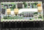
You will need a telephone line interface device such as Mitel/Zarlink MH88422. This device is used in TIM2015 (Speaking Clock) as described in Sam Hallas webpage http://www.samhallas.co.uk/repository/tim_2015.htm

These devices are obsolete now and gaetting hard to find. And you can only find them on Surplus semiconductor vendor sites. There is a long rigmarole to go through to buy them especially if you are outside the USA. I bought 10 at a cost of USD20 ea.

Mitel-MH88422-3.jpg
 

Modern telephones and answering machines use a microcontroller to sense line conditions, play messages, store dialing in memory, and injection of audio into telco lines.
Just use one of them and tap the signals on the board to your microcontroller. They comply with the Telco needs and available cheap if not behind your own spider webs.

An extraordinary learning book is the Motorola telecommunications data book, perhaps available on the web

----> https://archive.org/details/bitsavers_motoroladaCommunicationsDeviceData_83733780

Second one in the pile:

----> **broken link removed**
 

One can get a Modem chip for $12 https://datasheets.maximintegrated.com/en/ds/73M2901CE.pdf
But you still need all the impedance control parts (Xfmr etc) and a serial port. By the time you order and build it you can be up and running with a used modem or old PC at surplus cost.

Modems use DSP's not uC.
 

Status
Not open for further replies.

Part and Inventory Search

Welcome to EDABoard.com

Sponsor

Back
Top