cloner
Newbie level 3

Hello experts!
I am totally new to electronics and I need help with connecting the MQ135 Gas sensor with my raspberry pi 3B+ and with interpreting the data that the sensor provides. My main problem is that the sensor provides analog signals and the RPi 3B+ does not have a pin for analog signals.
Therefore I bought an ADC (ADS1115) with 16bit precision. I followed the following guide to read the data from the ADS1115 via python libraries on the RPi:
https://learn.adafruit.com/raspberry-pi-analog-to-digital-converters/ads1015-slash-ads1115
This way I can monitor the provided values from the analog inputs (AIN0 - AIN4). I do not understand what I am actually reading. The values fluctuate and with the GAIN parameter in the python script set to1 I get values in the range of 3000-5000 (but nothing is connected to the analog inputs of the ADC - so why do I see values at all?).
When I connect the AOUT pin of the MQ135 with AIN0 of the ADC the values from every analog input (AIN0 - AIN4) change - shouldn't only the value from AIN0 change?
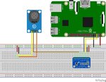
The breadboard looks like this:

In the scheme it says that it is the MQ9 - but I am using MQ135. The brown cable connects the analog out pin of the MQ135 with the AIN0 of the ADS1115.
The yellow calbe of the MQ135 is VCC and the orange cable is GND.
My questions:
1. Should I change something on the breadboard?
2. How should I interpret the data that the ADS1115 is providing?
3. Why is the ADS1115 reading signals when nothing is connected to AIN0 - AIN4?
I would also be very thankful if someone could maybe show me some sources which would help me to make further research.
Thank you!
I am totally new to electronics and I need help with connecting the MQ135 Gas sensor with my raspberry pi 3B+ and with interpreting the data that the sensor provides. My main problem is that the sensor provides analog signals and the RPi 3B+ does not have a pin for analog signals.
Therefore I bought an ADC (ADS1115) with 16bit precision. I followed the following guide to read the data from the ADS1115 via python libraries on the RPi:
https://learn.adafruit.com/raspberry-pi-analog-to-digital-converters/ads1015-slash-ads1115
This way I can monitor the provided values from the analog inputs (AIN0 - AIN4). I do not understand what I am actually reading. The values fluctuate and with the GAIN parameter in the python script set to1 I get values in the range of 3000-5000 (but nothing is connected to the analog inputs of the ADC - so why do I see values at all?).
When I connect the AOUT pin of the MQ135 with AIN0 of the ADC the values from every analog input (AIN0 - AIN4) change - shouldn't only the value from AIN0 change?
The breadboard looks like this:

In the scheme it says that it is the MQ9 - but I am using MQ135. The brown cable connects the analog out pin of the MQ135 with the AIN0 of the ADS1115.
The yellow calbe of the MQ135 is VCC and the orange cable is GND.
My questions:
1. Should I change something on the breadboard?
2. How should I interpret the data that the ADS1115 is providing?
3. Why is the ADS1115 reading signals when nothing is connected to AIN0 - AIN4?
I would also be very thankful if someone could maybe show me some sources which would help me to make further research.
Thank you!
