Confused about CMFB in one of Schreier's Amplifier

Status
Not open for further replies.

Julian18

Full Member level 3
Joined
Apr 9, 2007
Messages
167
Helped
5
Reputation
10
Reaction score
5
Trophy points
1,298
Activity points
2,389
Hi: all
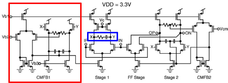
Now I am reading one of Schreier's paper: "A 375-mW Quadrature Bandpass Delta Sigma ADC With 8.5-MHz BW and 90-dB DR at 44 MHz". during reading, a question lingers. what is confusing me is the amplifier he used, more accurately, the CMFB. The amp is showed below
My question is the first stage CMFB(indicated by the red rectangular) seems got the feedback in the wrong direction, that is, IMO it is a CM feedforward..... I know maybe something dumb in my mind. so forgive me if I mess up...

Also could anybody point out what is the purpose of adding a series RC network(marked be blue rectangle) across the output of the first-stage amplifier. Is this amplifier specific? or just a functional part of the whole system(a Continuous Bandpass Sigmal-Delta AD)


Any help would be much appreciated.

Julian
 
Last edited:

A question to think about.
1) Yes it seems to me too from the circuit that the cmfb loop has a positive feedback.
2) CM feedforward: This is a common mode feedforward. I think the capacitor averager is used for compensating the cmfb loop by accomplishing this feedforward technique.
3) The series RC circuit introduces a zero to the differential circuit. I don't know why it is used. The series RC circuit will have an effect on the common mode loop response (if at all the common mode loop was a negative feedback one).
4) Is this amp specific? : Hmmm, I think this amplifier might be used within an integrator and not stand alone. I inferred that from the high differential DC gain it has.

Has this circuit not been explained atleast briefly in the paper?
PS: I might be wrong in my above inferences as I do not have access to the above paper. All the suggestions are based on my inferences of the circuit.
 
Last edited:
Hi amriths04
sorry about the CM feedforward stuff. what I really want to mean is Positive feedback.
when you see the capacitive CMFB path in 1st stage, that FB is negative. but the resistive CMFB path is positive based on what I have learned these years. maybe it is just a typo or what...
As to the original paper, it just give a brief comment on the circuit, as I quote it below
no explanation is given with regards to series RC.

Best Regards
Julian
 

The series RC is to compensate the amplifier because it is a two stage amplifier when looking from the input of IF to Op. Then there is another amplifier which is just a single stage amplifier the feedforward part, no compensate needed only one stage! The RC is used to not load the single stage amplifier, If normal miller compensation was used you would load the single stage amplifier while also compensating the two stage, not good if you want high GBW. Also it does look like a mistake on the CMFB 1, it is positive feedback, its a small mistake and could easily be made...If you are redesigning this just change it to negative

Jgk
 

Status
Not open for further replies.
Cookies are required to use this site. You must accept them to continue using the site. Learn more…