Continue to Site

Welcome to EDAboard.com

Welcome to our site! EDAboard.com is an international Electronics Discussion Forum focused on EDA software, circuits, schematics, books, theory, papers, asic, pld, 8051, DSP, Network, RF, Analog Design, PCB, Service Manuals... and a whole lot more! To participate you need to register. Registration is free. Click here to register now.

Complementary amplifier duty cycle, Mark & Space Ratio Pulse Width Modulation

Status
Not open for further replies.

stanleystan

Banned
Joined
Apr 26, 2014
Messages
59
Helped
2
Reputation
4
Reaction score
2
Trophy points
8
Activity points
0
To measure the duty cycle of a Complementary Amplifier that has two outputs Test points

Push Pull Duty cycle test:
Oscope channel#1 is on the High Logic State , amplifier channel#1
Oscope channel#2 is on the low logic state , amplifier channel#2

Use the Subtract function on the Oscope

This will give you the push pull duty cycle?

Most logic signals don't have two outputs or separate channels or output for the high logic state and the low logic state.

Non-Complementary logic signals:
How can this duty cycle test be done by using Oscope channel#1 for only the high logic state and Oscope channel#2 for the low logic state?
 

Is the ground of amplifier is connected to the oscilloscope by default ?

Otherwise you can just put the signal and ground wires of oscilloscope probe to two outputs and you can directly measure the duty cycle, no math, no subtraction.
 

In your first statement, using the subtract function will give you the difference between the two signals, i.e. the time difference between them will be shown as two narrow pulses.

The Time difference between them is the Duty Cycle time?

Or what is the time difference between them called? what kind of measurement is this?

Push Pull Duty cycle test:
Oscope channel#1 is on the High Logic State , amplifier channel#1
Oscope channel#2 is on the low logic state , amplifier channel#2

It's a Complementary amplifier that has Two separate outputs

Output#1 , is the high logic state
Output#2 , is the low logic state

Oscope channel#1 goes to amplifier output#1 which is the High Logic State
Oscope Channel#2 goes to amplfier output#2 which is the Low logic state

How do you get the duty cycle? use the subtract mode math function?
 

The Time difference between them is the Duty Cycle time?

Or what is the time difference between them called? what kind of measurement is this?

Hi most of the push pull amplifiers will be working in 50% always. can you post your schematic ?
 

Hi most of the push pull amplifiers will be working in 50% always.

That's for an audio amplifier

This is an Logic TTL or CMOS signals for a push pull for a servo amplifier

I'm trying to measure the duty cycle out of a push pull servo amplifier

How would you do this?

For some reasons AC or DC motors have a duty cycle other then 50% because they get to hot
 

This is an Logic TTL or CMOS signals for a push pull for a servo amplifier
I'm trying to measure the duty cycle out of a push pull servo amplifier
I got your question now.

How would you do this?
Its not a thing to worry about. But you can measure the output only when a load is connected in the terminals. otherwise you have to connect a dummy load (a resistor) on the output.

In the beginning the method will also work for you. but the easiest method is connecting the oscilloscope ground to one output and signal to other output (parallel to load). and you can just measure the dutycycle in oscilloscope.
 

It's a Complementary amplifier that has Two separate outputs

Output#1 , is the high logic state
Output#2 , is the low logic state

Oscope channel#1 goes to amplifier output#1 which is the High Logic State
Oscope Channel#2 goes to amplfier output#2 which is the Low logic state

How do you get the duty cycle? use the subtract mode math function?

But i want to try it this way, will this work?
 

But i want to try it this way, will this work?
Yeah, It will.

Conditions :
1, The circuit should be properly grounded with Oscilloscope.
2, There should be a load or dummy load in the output.
3, you should take care of if any reversing in voltage, according to the driver.
 

The difference between the two Oscope channels will be the duty cycle?

The Time difference between oscope channel#1 and channel#2 is the duty cycle?
 

The difference between the two Oscope channels will be the duty cycle?
No. the difference between two channels is a signal. which has high(ON time) and low(OFF time).

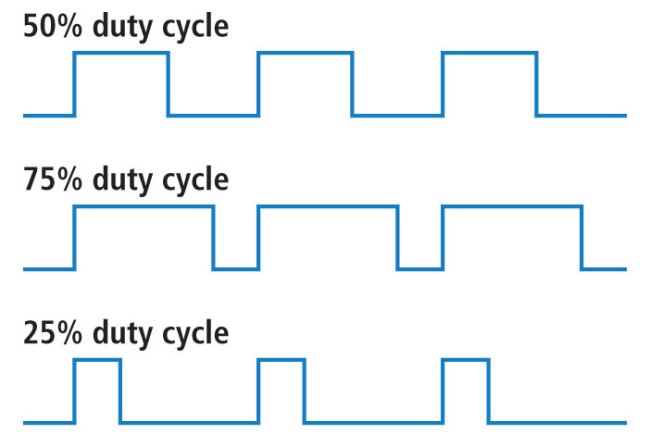
duty cycle = ON time / (ON time + OFF time)

512e869bce395fbc64000002.JPG


Some oscilloscopes will have a inbuild function for measuring the dutycycle.
 

Re: Complementary amplifier duty cycle, Mark & Space Ratio Pulse Width Modulation

Differential Measurement:
O-scope channel#1 goes to only to the ON TIME of the logic signal
O-scope channel#2 goes to only to the OFF TIME of the logic signal

How can this be done with only one output?

I would need to put a forward diode on the Oscope probe to only get the ON TIME of the logic signal for channel#1

For channel#2 I would need to put a reverse diode on the Oscope probe to only get the OFF TIME of the logic signal?

- - - Updated - - -

No. the difference between two channels is a signal. which has high(ON time) and low(OFF time).

Yes it says in my book to measure the Period of the logic signal

Then you set the Oscope to get "the difference" between two Oscope channels

The difference between the ON time and the OFF time is what? the duty cycle or what is it?

Once you got the difference of the ON time and OFF time , you adjust the input signal to 40% of the period time

I'm not sure why they want 40% of the period time from the difference of the On time and off time

It's for a servo amplifier
 

Differential Measurement:
O-scope channel#1 goes to only to the ON TIME of the logic signal
O-scope channel#2 goes to only to the OFF TIME of the logic signal

How can this be done with only one output?
#2
I would need to put a forward diode on the Oscope probe to only get the ON TIME of the logic signal for channel#1

For channel#2 I would need to put a reverse diode on the Oscope probe to only get the OFF TIME of the logic signal?
#5, post your schematic.

The difference between the ON time and the OFF time is what? the duty cycle or what is it?
Not the difference.
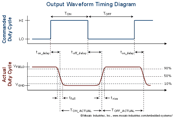
Duty cycle = ( Ton / T ) * 100 %

Ton = ON time
Toff = OFF time
T = Period (Ton + Toff)
 

Re: Complementary amplifier duty cycle, Mark & Space Ratio Pulse Width Modulation

Ton= ON time
Toff = OFF time

The Difference is what?

- - - Updated - - -

T = Period (Ton + Toff)

Yes i know, but the difference of the ON TIME and OFF TIME is what?
 

If the output is high It is called ON time, If the output is low it is called OFF time.

Yes i know this

But what is called when you measure the Difference of the ON TIME and the OFF TIME?

If the ON Time and OFF Time is 50% duty cycle, the difference is zero

If the ON time and Off time is 30% duty cycle, the difference is

On Time is 50milliseconds
Off Time Is 10milli-seconds
The difference is 40 milliseconds?
 

But what is called when you measure the Difference of the ON TIME and the OFF TIME?

you mean Ton - Toff, I never seen this expression. Also I don see the importance of this. because it will not desire the operation of any load.
Ton = 50ms
Toff = 10ms
Ton - Toff = 40ms
Ton = 100ms
Toff = 60ms
Ton - Toff = 40ms

Its percentage also comes in the range of -100% to 100% thats also have no meaning.
 

stanleystan, your questins are very vague but I think what you are asking for is the word 'ratio'. Sometimes called 'mark to space ratio'. The on time and off time must add to 100% so sometimes only one of them is given, the other can always be calculated by subtracting from 100.

Brian.
 

Sometimes called 'mark to space ratio'

When does a tech use Mark to Space ratio, for what kind of circuits or applications?

How is measuring the Mark to Space times durations differ from measuring the time period, pulse width?

Mark = On Time
Space = Off time
Mark & Space ratio is ? the duty cycle? or is it something different?

When would I ever use the Mark & Space Ratio?
 

There is no specific reason for using mark to space ratio.

It is often used as the ratio of
on time : Off time
It is a another form of representation of Duty cycle.
 

Status
Not open for further replies.

Similar threads

Part and Inventory Search

Welcome to EDABoard.com

Sponsor

Back
Top