yefj
Advanced Member level 5

- Joined
- Sep 12, 2019
- Messages
- 1,549
- Helped
- 1
- Reputation
- 2
- Reaction score
- 5
- Trophy points
- 38
- Activity points
- 9,336
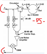
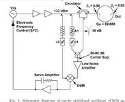
Hello, I have built a system shown below by the attached article.Its a frequency locked loop.
basicky I am using a YIG as VCO to tune it exactly to the cavity resonator.
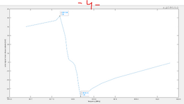
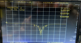
The phase and amplitude of the resonance shown below.
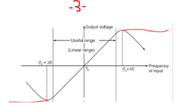
The mixer acts as a frequency discriminator by the behavior in photo 3.
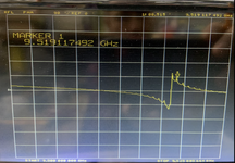
So if we input a tone at some frequency and look what IF (error voltage) we get at point B as shown in photo 4 and 5 .
The main problem I have is the YIG VCO.
The YIG has two coils which we tune.
A large coil call "tune" and a small coil called FM.
The large "tune" coil is being fed near the resonance area,while the smaller FM coil is the coil I use to tune the error of the mixer IF (frequency discriminator) which compares the signal coming from the cavity resonator and the signal coming from the YIG.
The second coil is FM coil:
1.5uH inductance and 1Ohm resistance FM coil.
sensitivity 400Khz/mA
The main problem is that I am tuning the error using the FM coil while the tune coil (which is biased by constant voltage) is not in the feedback fixing mechanism I only have the FM coil to compensate for the gap between the YIG and cavity signals.
I was told to use a PI controller(between the IF output and YIG input )to compensate fro the tune drifting.
Is there some strategy on how what parameters the PI controller should have to compensate for the exteral frequency drifting caused by the tune coil?
Thanks.
Attachments
-
High_spectral_purity_microwave_oscillator_design_using_conventional_air-dielectric_cavity (4).pdf563.8 KB · Views: 23
-
 1735587613743.png68.4 KB · Views: 25
 -
 1735587543600.png71.9 KB · Views: 19
 -
 1735587393237.png71.2 KB · Views: 19
 -
 1735586950930.png1.4 MB · Views: 17
 -
 1735586909221.png1.6 MB · Views: 22
 -
 1735586527116.png115.6 KB · Views: 21