FreshmanNewbie
Advanced Member level 1

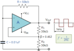
I have this comparator circuit using an op-amp. This is my actual op-amp used in the circuit. I have used TL072 as I didn't have the simulation model.

This circuit is used to trigger the output when the inverting input is less than 80% of the non-inverting input.
But, when I use this in actual circuit, when the inverting input is less than 80% of the non-inverting input, the output is oscillating, even though the circuit is designed for hysteresis.
I read this application note from TI, but I am not sure why the output is oscillating. Can someone tell me the reasons why the output might be oscillating?
In actual circuit measurement, the input at the non-inverting node, has an oscillation of 1.4V peak to peak. I believe this is the reason why the output is also oscillating.
But I am not sure on why the input is also oscillating. I have no capacitors also in the entire circuit.
Can someone tell me the reasons and how to avoid this oscillation?


