Continue to Site

Welcome to EDAboard.com

Welcome to our site! EDAboard.com is an international Electronics Discussion Forum focused on EDA software, circuits, schematics, books, theory, papers, asic, pld, 8051, DSP, Network, RF, Analog Design, PCB, Service Manuals... and a whole lot more! To participate you need to register. Registration is free. Click here to register now.

Common base audio amplifier with ositive feedback

Status
Not open for further replies.

neazoi

Advanced Member level 6
Joined
Jan 5, 2008
Messages
4,155
Helped
13
Reputation
26
Reaction score
15
Trophy points
1,318
Location
Greece
Activity points
37,164

Audio amps normally use negative feedback to reduce distortion. It also reduces the gain and widens the frequency response. Positive feedback would make the distortion and frequency response worse.

The hearing aid you showed uses negative feedback, but only to stabilize the DC operating point. At audio frequencies the feedback current is shunted to ground by the 10uF capacitor.

Yes I know that. In a shortwave radio application distortion and bandwidth may be not much of an issue like sensitivity.
The single transistor circuit **broken link removed** is a regenerative audio amplifier.
I would like something like this to be made but I am totally unaware of the components values. Also I have not found any practical circuit on the net. Any sources?
 

The single transistor circuit **broken link removed** is a regenerative audio amplifier.
Unfortunately it's not too well thought out, and won't work. It's actually not possible to use positive feedback to increase the gain of a one transistor amplifier without using a tuned circuit or transformer.

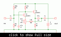
The two transistor circuit they show is better but not very practical. If you want to experiment with positive feedback, the circuit below should work well.

Positive feedback is through R6. The potentiometer determines how much feedback is applied to the first transistor. With no feedback, the voltage gain is about two. As the potentiometer is turned to increase the feedback, the gain will rise until the circuit becomes unstable and starts to oscillate.

Input impedance is about 25K and the output impedance is low, so it's compatible with any ordinary audio equipment. The output is limited to about 1.5V RMS though, before clipping.

I think the reason you can't find references or practical schematics on the net is because positive feedback isn't used in audio equipment because it isn't useful.


Thank you very much!
Such amplifiers could be usefull in very low component count receivers, mostly regenerative, to ensure good gain with less components (I hope so). Instead of having the regenerative RF stage do the audio job as well (reflex) to have a separate audio amplifier. I am thinking of how well it could perform in regenerative receivers...
 

You can reduce component count by using the same transistor to amplify both RF and AF but positive feedback really is not useful for audio amplifiers.

The only reason the previous circuit allows the gain to be increased in a fairly predictable manner with positive feedback is that the open-loop gain is heavily reduced by local negative feedback in the first place.

You can get higher gain more easily and predictably by using less negative feedback, or none at all. With a single transistor, you can get close to 40dB of voltage gain.

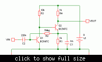
A circuit like the one below gives about 75dB of gain (times 5000) without any feedback, positive or negative.


What are the input and output impedances? Maybe one could achieve even more gain with a third transistor?
 

What are the input and output impedances?
Input impedance is about 10K to 20K, depending on the first transistor. Output impedance is 1K (defined by R4).

Maybe one could achieve even more gain with a third transistor?
Of course you can! People have been designing circuits with more than two transistors for over half a century.

What is the point of all this? How much gain do you need?
 

Input impedance is about 10K to 20K, depending on the first transistor. Output impedance is 1K (defined by R4).


Of course you can! People have been designing circuits with more than two transistors for over half a century.

What is the point of all this? How much gain do you need?

Just enough to amplify the audio from an RF detector to drive high impedance headphones. 75db gain is huge! compared to the ~35 of an LM386!
Is C1 is 1mF or 1uF?
 

C1 is 1000uF i.e. 1mF.
There should be a capacitor between the output and the headphones too (maybe 10uF).
 

C1 is 1000uF i.e. 1mF.
There should be a capacitor between the output and the headphones too (maybe 10uF).

Thank you very much, it will be fun to try this at home!
 

The single transistor circuit **broken link removed** is a regenerative audio amplifier.
I think, you are jumping into conclusions. The paper isn't taking about audio or audio amplifiers. The purpose of the specific circuit isn't really clear, I understand that it isn't but an illustration of the broad idea of positive feedback, without referring to a particular application.
 

You can reduce component count by using the same transistor to amplify both RF and AF but positive feedback really is not useful for audio amplifiers.

The only reason the previous circuit allows the gain to be increased in a fairly predictable manner with positive feedback is that the open-loop gain is heavily reduced by local negative feedback in the first place.

You can get higher gain more easily and predictably by using less negative feedback, or none at all. With a single transistor, you can get close to 40dB of voltage gain.

A circuit like the one below gives about 75dB of gain (times 5000) without any feedback, positive or negative.


I have built this preamp and it works great. how could I transform it to use ordinary modern headphones? I think these are 32 ohm?
Is it enough to change the colector resistor from 1k to 32r? what will be the impact on gain?
 

Hello, sorry to open this topic again.
How should I vary the gain of this amplifier from about zero to maximum without using a potentiometer on the input?
 

Regular feeback can't reduce the gain below unity.
 
  • Like
Reactions: neazoi

    neazoi

    Points: 2
    Helpful Answer Positive Rating
Regular feeback can't reduce the gain below unity.
WOW that was quick FvM :)
Ok, so is there any way to reduce gain at an amount by varying some resistors? maybe the 10k one?
 

Status
Not open for further replies.

Part and Inventory Search

Welcome to EDABoard.com

Sponsor

Back
Top