Continue to Site

Welcome to EDAboard.com

Welcome to our site! EDAboard.com is an international Electronics Discussion Forum focused on EDA software, circuits, schematics, books, theory, papers, asic, pld, 8051, DSP, Network, RF, Analog Design, PCB, Service Manuals... and a whole lot more! To participate you need to register. Registration is free. Click here to register now.

Colpitts-Clapp overtone crystal oscillator

Status
Not open for further replies.

andrea_mori

Member level 2
Member level 2
Joined
Aug 14, 2012
Messages
44
Helped
0
Reputation
0
Reaction score
0
Trophy points
1,286
Activity points
1,727
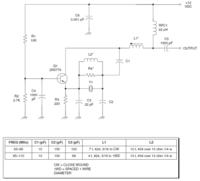
Attached the circuit I'm using successfully with 3rd overtone crystal at 45.1584 Mhz (C1=C2=22 pF, L3=2.7uH).

I'm trying to use it at 90.3168 MHz, using a 5th overtone crystal, but it doesn't start at the right frequency.
C1 and C2, scaled to 12 pF, show the same reactance, C2 and L3 are tuned around 60 MHz, so they look inductive at 3rd overtone but still capacitive a 5th overtone.

45 Mhz crystal has the following specs:
mode: 3rd overtone
ESR: 15 ohm
motional capacitance: 1.2 fF
Q: 200k

while 90 MHz crystal specs are:
mode: 5th overtone
ESR: 35 ohm
motional capacitance: 0.36 fF
Q: 135k

So, the relevant difference between the two crystal is the ESR, 15 ohm against 35 ohm.

Seems there isn't enough gain to start.

Any help?
 

Attachments

  • 90_MHz.JPG
    90_MHz.JPG
    27.7 KB · Views: 380

Attached the circuit I'm using successfully with 3rd overtone crystal at 45.1584 Mhz (C1=C2=22 pF, L3=2.7uH).

I'm trying to use it at 90.3168 MHz, using a 5th overtone crystal, but it doesn't start at the right frequency.
C1 and C2, scaled to 12 pF, show the same reactance, C2 and L3 are tuned around 60 MHz, so they look inductive at 3rd overtone but still capacitive a 5th overtone.

45 Mhz crystal has the following specs:
mode: 3rd overtone
ESR: 15 ohm
motional capacitance: 1.2 fF
Q: 200k

while 90 MHz crystal specs are:
mode: 5th overtone
ESR: 35 ohm
motional capacitance: 0.36 fF
Q: 135k

So, the relevant difference between the two crystal is the ESR, 15 ohm against 35 ohm.

Seems there isn't enough gain to start.

Any help?

Sorry. no circuit attached. Did you try to adjust transistor base bias? In my oscillators, this was always critical, except crystals.

- - - Updated - - -

Now I can see it. The diode should set the amplitude, bu may be it prevents starting. I would try to connect its "cold" side to a potentiometer by which channel current can be set to a good value for starting.
 

Have you taken into account the shunting effect to ground of the crystal's holder capacitance at 90 MHz? Do you have an accurate model of the crystal which includes this capacitance?
 
Last edited:

On overtone frequency, Butler oscillator is working better than Colpitts.


I have used this emitter coupled harmonic circuit before with a 91.8 MHz crystal as part of a 918 MHz test set. It works well and is very stable.
 

Attachments

  • em_coupl.png
    em_coupl.png
    23.9 KB · Views: 347

Have you taken into account the shunting effect to ground of the crystal's holder capacitance at 90 MHz? Do you have an accurate model of the crystal which includes this capacitance?

This is not a simulation, I'm testing the oscillator with its real PCB.

- - - Updated - - -

Sorry. no circuit attached. Did you try to adjust transistor base bias? In my oscillators, this was always critical, except crystals.

- - - Updated - - -

Now I can see it. The diode should set the amplitude, bu may be it prevents starting. I would try to connect its "cold" side to a potentiometer by which channel current can be set to a good value for starting.

I'll give a try removing temporarily the schottky diode from the circuit, and eventually I'll try changing the bias of the jfet.
I have not understood how connect the potentiometer, could you explain?
Thanks
 

This is not a simulation, I'm testing the oscillator with its real PCB.

I am aware that you are trying it on a pcb, but the correct way of investigating start-up problems is to do an open-loop gain/phase analysis to see if there is enough loop gain at phase zero crossing for this to start up. For this, it helps to have a reasonable accurate model of the crystal. That can be easily measured if you have the right tools.

**broken link removed**
 

The crystal has been already measured, these are its parameters:
motional resistance: 36.9 ohm
motional capacitance: 0.353 fF
motional inductance: 8.8 mH
shunt capacitance: 2.64 pF

I have experimented a little: c1 and c2 are 10 pF, L3 removed from the circuit.
The oscillator starts at 54 MHz, the 3rd overtone, so there is enough negative resistance to overcome the motional resistance (36.9 ohm).
Then I placed L3, 470 nH, tuning it with C2 at around 73 MHz, between the 3rd and the 5th overtone. so they look inductive at 3rd overtone (j 347 ohm) but still capacitive a 5th overtone(-j 528 ohm).
The oscillator does not start. Maybe the negative resistance at 90 MHz is not enough. I calculated around -j 104 ohm. Also L3 is in parallel, so the total negative resistance seen from the crystal decreases again down to -j 88 ohm.
Jfet's transconductance does not help (12 mA/V).
 

I am aware that you are trying it on a pcb, but the correct way of investigating start-up problems is to do an open-loop gain/phase analysis to see if there is enough loop gain at phase zero crossing for this to start up. For this, it helps to have a reasonable accurate model of the crystal. That can be easily measured if you have the right tools.

**broken link removed**

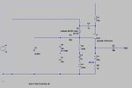
Attached the simulation of the oscillator using the measured model of the crystal.
Simulating the circuit, the oscillator start at the right frequency.
But in real world it does not start.
Any suggestion?
Sim.jpgSim_Sin.jpgSim_startup.jpg
 

Status
Not open for further replies.

Part and Inventory Search

Welcome to EDABoard.com

Sponsor

Back
Top