Continue to Site

Welcome to EDAboard.com

Welcome to our site! EDAboard.com is an international Electronics Discussion Forum focused on EDA software, circuits, schematics, books, theory, papers, asic, pld, 8051, DSP, Network, RF, Analog Design, PCB, Service Manuals... and a whole lot more! To participate you need to register. Registration is free. Click here to register now.

code for pacemaker device

Status
Not open for further replies.

mshh

Full Member level 6
Full Member level 6
Joined
May 30, 2010
Messages
349
Helped
0
Reputation
0
Reaction score
0
Trophy points
1,296
Location
usa
Activity points
3,871
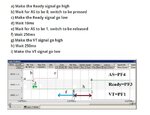
I am trying o write a code for this emulated pacemaker device, but i couldn't i need some help. the requirement in the attached pic
Code:
if (SW1==0x10){

//if(GPIO_PORTF_DATA_R &= ~0x08){
	        Delay1ms(250); // 
					  GPIO_PORTF_DATA_R |= 0x02;       // LED is on
								 Delay1ms(250); // 
			  GPIO_PORTF_DATA_R &= ~0x02;       // LED is off
				//GPIO_PORTF_DATA_R |= 0x08;       // LED green is on
	
//}
}else{
				GPIO_PORTF_DATA_R &= ~0x08;       // LED green is on
       	 Delay1ms(10); // 

}
 

Attachments

  • 1g.jpg
    1g.jpg
    88.4 KB · Views: 182

Tiva TM4C123GH6PM controller? Or which Tiva or Stellaris controller.

If Tiva/Stellaris then as you are using PORTF you need to unlock the port and configure the port and then lock it.

Are you using SysTick() to make delay function or not?

Show full code so that it can be fixed. Better zip and post the complete Keil project files.
 

yes, it's TM4C123GH6PM. i have already initialized the port i think it's a code problem. I used delay in software not timer.
 

Attachments

  • Lab7_HeartBlock.rar
    103.2 KB · Views: 135

Where is Ready signal connected to and from where it comes?

I guess your professor has asked you to use external interrupt to detect Ready signal state?

Are you using TM4C123GXL launchapad development board?

https://users.ece.utexas.edu/~valvano/Volume1/E-Book/

https://users.ece.utexas.edu/~valvano/Volume1/E-Book/C6_MicrocontrollerPorts.htm

Show your circuit. I need to see your Switch connections and Ready Signal connection.


Edit:

I see in code comments (Delay function) that you are using 80 MHz clock but I don't see PLL enabled.

Refer example projects to setup PLL to get 80 MHz clock.

https://users.ece.utexas.edu/~valvano/arm/

I see from your code that you are using TExaS.h file which is a part of Valvano examples and books related to Tiva programming. The author uses TM4C123GXL launchpad.

Provide more details about your actual project requirements so that I can help you with it.

- - - Updated - - -

Here is the completed code.

Test and reply if this works.


Code C - [expand]
1
2
3
4
5
6
7
8
9
10
11
12
13
14
15
16
17
18
19
20
21
22
23
24
25
26
27
28
29
30
31
32
33
34
35
36
37
38
39
40
41
42
43
44
45
46
47
48
49
50
51
52
53
54
55
56
57
58
59
60
61
62
63
64
65
66
67
68
69
70
71
72
73
74
75
76
77
78
79
80
81
82
83
84
85
86
87
88
89
90
91
92
93
94
95
96
97
98
99
100
101
102
103
104
105
106
107
108
109
110
111
112
113
114
115
116
117
118
119
120
121
122
123
124
125
126
127
128
129
130
131
132
133
134
135
136
137
138
139
140
141
142
143
144
145
146
147
148
149
150
151
152
153
154
155
156
157
158
159
160
161
162
163
164
165
166
167
168
169
170
171
172
173
174
175
176
177
178
179
180
181
182
183
184
185
186
187
188
189
190
191
192
193
194
195
196
197
198
199
200
201
202
203
204
205
206
207
208
209
210
211
212
213
214
215
216
217
218
219
220
221
222
223
224
225
226
227
228
229
230
231
232
233
234
// 0.Documentation Section 
// Lab7_HeartBlock, main.c
 
// Runs on LM4F120 or TM4C123 LaunchPad
// Input from PF4(SW1) is AS (atrial sensor), 
// Output to PF3, Green LED, is Ready,
// Output to PF1, Red LED, is VT (ventricular trigger) 
// Make PF4 input, PF3,PF1 output
// Initialize Ready to high and VT to low
// Repeat this sequence of operation over and over
// 1) Wait for AS to fall (touch SW1 switch)
// 2) Clear Ready low
// 3) Wait 10ms (debounces the switch)
// 4) Wait for AS to rise (release SW1)
// 5) Wait 250ms (simulates the time between atrial and ventricular contraction)
// 6) set VT high, which will pulse the ventricles 
// 7) Wait 250ms
// 8) clear VT low 
// 9) set Ready high
 
// Date: January 15, 2016
 
#include <stdio.h>
#include <stdint.h>
#include <stdlib.h>
#include "tm4c123gh6pm.h"
#include "PLL.h"
#include "SysTick.h"
#include "TExaS.h"
 
#define AS    (*((volatile unsigned long *)0x40025040))
#define READY (*((volatile unsigned long *)0x40025020))
#define VT      (*((volatile unsigned long *)0x40025008))
 
// 2. Declarations Section
//   Global Variables
//unsigned long SW1;  // input from PF4
 
//   Function Prototypes
void PortF_Init(void);
void Delay1ms(unsigned long msec);
void EnableInterrupts(void);  // Enable interrupts
void WaitForASLow(void);
void WaitForASHigh(void);
void SetVT(void);
void ClearVT(void);
void SetReady(void);
void ClearReady(void);
 
void Delay_1ms(unsigned long msec);
 
// 3. Subroutines Section
// MAIN: Mandatory for a C Program to be executable
int main(void){
  //TExaS_Init(SW_PIN_PF40,LED_PIN_PF31,ScopeOn);  // activate grader and set system clock to 80 MHz
  PortF_Init();                        // Init port PF4 PF3 PF1
 
    PLL_Init();
    SysTick_Init();
    
  //EnableInterrupts();                  // enable interrupts for the grader
  
  while(1){          // Follows the nine steps list above
    // a) Ready signal goes high
    // b) wait for switch to be pressed
    // c) Ready signal goes low
    // d) wait 10ms
    // e) wait for switch to be released
    // f) wait 250ms
    // g) VT signal goes high
    // h) wait 250ms
    // i) VT signal goes low
            SetReady();
            WaitForASLow();
            ClearReady();
            Delay_1ms(10);
            WaitForASHigh();
            Delay_1ms(250);
            SetVT();
            Delay_1ms(250);
            ClearVT();
        
            /*
            SW1 = GPIO_PORTF_DATA_R &0x10;   // put PF4 into SW1
            GPIO_PORTF_DATA_R |= 0x08;       // LED green is on
 
            do
            {
            Delay1ms(250);  
                    GPIO_PORTF_DATA_R |= 0x02;   // LED is on
                    Delay1ms(250);  
                    GPIO_PORTF_DATA_R &= ~0x02;  // LED is off
                    GPIO_PORTF_DATA_R |= 0x08;   // LED green is on
            }while(SW1 == 1);
 
 
            GPIO_PORTF_DATA_R &= ~0x08;      // LED green is on
      Delay1ms(10);
            */
 
    }
 
 
  }
//}
// Subroutine to initialize port F pins for input and output
// PF4 is input SW1 and PF3-1 is output LEDs
// Inputs: None
// Outputs: None
// Notes: ...
void PortF_Init(void){ 
    volatile unsigned long delay;
  SYSCTL_RCGC2_R |= 0x00000020;     // 1) activate clock for Port F
  delay = SYSCTL_RCGC2_R;           // allow time for clock to start
  GPIO_PORTF_LOCK_R = 0x4C4F434B;   // 2) unlock GPIO Port F
  GPIO_PORTF_CR_R = 0x1E;           // allow changes to PF4-1  
  GPIO_PORTE_AMSEL_R &= ~0xFF;      // 3) disable analog function
  GPIO_PORTF_DIR_R &= ~0x10;        // 4.1) PF4 input,
  GPIO_PORTF_DIR_R |= 0x0E;         // 4.2) PF3,2,1 output
    GPIO_PORTE_AFSEL_R &= ~0xFF;      // 5) not alternative
  GPIO_PORTF_AFSEL_R = 0x00;        // 6) disable alt function
  GPIO_PORTF_PUR_R = 0x10;          // enable pull-up on PF4
  GPIO_PORTF_DEN_R = 0x1E;          // 7) enable digital I/O on PF4-1
}
// Color    LED(s) PortF
// dark     ---    0
// red      R--    0x02
// blue     --B    0x04
// green    -G-    0x08
// yellow   RG-    0x0A
// sky blue -GB    0x0C
// white    RGB    0x0E
 
 
// Subroutine reads AS input and waits for signal to be low
// If AS is already low, it returns right away
// If AS is currently high, it will wait until it to go low
// Inputs:  None
// Outputs: None
void WaitForASLow(void){
// write this function
    while(GPIO_PORTF_DATA_R & 0x10) {           
            Delay_1ms(50);
    }
}
 
// Subroutine reads AS input and waits for signal to be high
// If AS is already high, it returns right away
// If AS is currently low, it will wait until it to go high
// Inputs:  None
// Outputs: None
void WaitForASHigh(void){
// write this function
    while(!(GPIO_PORTF_DATA_R & 0x10)) {            
            Delay_1ms(50);
    }
}
 
// Subroutine sets VT high
// Inputs:  None
// Outputs: None
// Notes:   friendly means it does not affect other bits in the port
void SetVT(void){
// write this function
    VT = 0x02;
}
 
// Subroutine clears VT low
// Inputs:  None
// Outputs: None
// Notes:   friendly means it does not affect other bits in the port
void ClearVT(void){
// write this function
    VT = 0x00;
}
 
// Subroutine sets Ready high
// Inputs:  None
// Outputs: None
// Notes:   friendly means it does not affect other bits in the port
void SetReady(void){
// write this function
    READY = 0x08;
}
 
 
// Subroutine clears Ready low
// Inputs:  None
// Outputs: None
// Notes:   friendly means it does not affect other bits in the port
void ClearReady(void){
// write this function
    READY = 0x00;
}
 
// Subroutine to delay in units of milliseconds
// Inputs:  Number of milliseconds to delay
// Outputs: None
// Notes:   assumes 80 MHz clock
void Delay1ms(unsigned long msec){
// write this function
    unsigned long count;
  while(msec > 0 ) { // repeat while there are still ms to delay
    count = 16000; // number of counts to delay 1ms at 80MHz
    while (count > 0) { 
      count--;
    } // This while loop takes approximately 3 cycles
    msec--;
  }
}
 
void Delay100ms(void) {
    unsigned long volatile time;
    
  time = (727240 * 200 / 91);  // 0.1sec
    
  while(time) {
    time--;
  }
}
 
void Delay_1ms(unsigned long msec) {
    unsigned long count;
    
    while(msec) {
        count = 13333;
        
        while(count) {
          count--;
        }
        
        msec--;
    }
}


- - - Updated - - -

There was a mistake in PortF_Init() code which I modified. Fixed it and tested on hardware and working fine.


Code C - [expand]
1
2
3
4
5
6
7
8
9
10
11
12
13
14
15
16
17
18
19
20
21
22
23
24
25
26
27
28
29
30
31
32
33
34
35
36
37
38
39
40
41
42
43
44
45
46
47
48
49
50
51
52
53
54
55
56
57
58
59
60
61
62
63
64
65
66
67
68
69
70
71
72
73
74
75
76
77
78
79
80
81
82
83
84
85
86
87
88
89
90
91
92
93
94
95
96
97
98
99
100
101
102
103
104
105
106
107
108
109
110
111
112
113
114
115
116
117
118
119
120
121
122
123
124
125
126
127
128
129
130
131
132
133
134
135
136
137
138
139
140
141
142
143
144
145
146
147
148
149
150
151
152
153
154
155
156
157
158
159
160
161
162
163
164
165
166
167
168
169
170
171
172
173
174
175
176
177
178
179
180
181
182
183
184
185
186
187
188
189
190
191
192
193
194
195
196
197
198
199
200
201
202
203
204
205
206
207
208
209
210
211
212
213
214
215
216
217
218
219
220
221
222
223
224
225
226
227
228
229
230
231
232
233
234
235
236
237
// 0.Documentation Section 
// Lab7_HeartBlock, main.c
 
// Runs on LM4F120 or TM4C123 LaunchPad
// Input from PF4(SW1) is AS (atrial sensor), 
// Output to PF3, Green LED, is Ready,
// Output to PF1, Red LED, is VT (ventricular trigger) 
// Make PF4 input, PF3,PF1 output
// Initialize Ready to high and VT to low
// Repeat this sequence of operation over and over
// 1) Wait for AS to fall (touch SW1 switch)
// 2) Clear Ready low
// 3) Wait 10ms (debounces the switch)
// 4) Wait for AS to rise (release SW1)
// 5) Wait 250ms (simulates the time between atrial and ventricular contraction)
// 6) set VT high, which will pulse the ventricles 
// 7) Wait 250ms
// 8) clear VT low 
// 9) set Ready high
 
// Date: January 15, 2016
 
#include <stdio.h>
#include <stdint.h>
#include <stdlib.h>
#include "tm4c123gh6pm.h"
#include "PLL.h"
//#include "SysTick.h"
//#include "TExaS.h"
 
#define AS    (*((volatile unsigned long *)0x40025040))
#define READY (*((volatile unsigned long *)0x40025020))
#define VT      (*((volatile unsigned long *)0x40025008))
 
// 2. Declarations Section
//   Global Variables
//unsigned long SW1;  // input from PF4
 
//   Function Prototypes
void PortF_Init(void);
void Delay1ms(unsigned long msec);
void EnableInterrupts(void);  // Enable interrupts
void WaitForASLow(void);
void WaitForASHigh(void);
void SetVT(void);
void ClearVT(void);
void SetReady(void);
void ClearReady(void);
 
void Delay_1ms(unsigned long msec);
 
// 3. Subroutines Section
// MAIN: Mandatory for a C Program to be executable
int main(void){
  //TExaS_Init(SW_PIN_PF40,LED_PIN_PF31,ScopeOn);  // activate grader and set system clock to 80 MHz
  PortF_Init();                        // Init port PF4 PF3 PF1
 
    PLL_Init();
    //SysTick_Init();
    
  //EnableInterrupts();                  // enable interrupts for the grader
  
  while(1){          // Follows the nine steps list above
    // a) Ready signal goes high
    // b) wait for switch to be pressed
    // c) Ready signal goes low
    // d) wait 10ms
    // e) wait for switch to be released
    // f) wait 250ms
    // g) VT signal goes high
    // h) wait 250ms
    // i) VT signal goes low
            //GPIO_PORTF_DATA_R = 0x0E;
                    
            SetReady();
            WaitForASLow();
            ClearReady();
            Delay_1ms(10);
            WaitForASHigh();
            Delay_1ms(250);
            SetVT();
            Delay_1ms(250);
            ClearVT();
                    
            /*
            SW1 = GPIO_PORTF_DATA_R &0x10;   // put PF4 into SW1
            GPIO_PORTF_DATA_R |= 0x08;       // LED green is on
 
            do
            {
            Delay1ms(250);  
                    GPIO_PORTF_DATA_R |= 0x02;   // LED is on
                    Delay1ms(250);  
                    GPIO_PORTF_DATA_R &= ~0x02;  // LED is off
                    GPIO_PORTF_DATA_R |= 0x08;   // LED green is on
            }while(SW1 == 1);
 
 
            GPIO_PORTF_DATA_R &= ~0x08;      // LED green is on
      Delay1ms(10);
            */
 
    }
 
 
  }
//}
// Subroutine to initialize port F pins for input and output
// PF4 is input SW1 and PF3-1 is output LEDs
// Inputs: None
// Outputs: None
// Notes: ...
void PortF_Init(void){ 
    volatile unsigned long delay;
  SYSCTL_RCGC2_R |= 0x00000020;     // 1) activate clock for Port F
  delay = SYSCTL_RCGC2_R;           // allow time for clock to start
  GPIO_PORTF_LOCK_R = 0x4C4F434B;   // 2) unlock GPIO Port F
  GPIO_PORTF_CR_R = 0x1F;           // allow changes to PF4-1  
  GPIO_PORTF_AMSEL_R &= ~0xFF;      // 3) disable analog function
    GPIO_PORTF_PCTL_R = 0x00000000;   // 4) PCTL GPIO on PF4-0
  //GPIO_PORTF_DIR_R &= ~0x10;        // 4.1) PF4 input,
  GPIO_PORTF_DIR_R = 0x0E;         // 4.2) PF3,2,1 output
    //GPIO_PORTE_AFSEL_R &= ~0xFF;      // 5) not alternative
  GPIO_PORTF_AFSEL_R = 0x00;        // 6) disable alt function
  GPIO_PORTF_PUR_R = 0x10;          // enable pull-up on PF4
  GPIO_PORTF_DEN_R = 0x1E;          // 7) enable digital I/O on PF4-1
}
// Color    LED(s) PortF
// dark     ---    0
// red      R--    0x02
// blue     --B    0x04
// green    -G-    0x08
// yellow   RG-    0x0A
// sky blue -GB    0x0C
// white    RGB    0x0E
 
 
// Subroutine reads AS input and waits for signal to be low
// If AS is already low, it returns right away
// If AS is currently high, it will wait until it to go low
// Inputs:  None
// Outputs: None
void WaitForASLow(void){
// write this function
    while(GPIO_PORTF_DATA_R & 0x10) {           
            Delay_1ms(50);
    }
}
 
// Subroutine reads AS input and waits for signal to be high
// If AS is already high, it returns right away
// If AS is currently low, it will wait until it to go high
// Inputs:  None
// Outputs: None
void WaitForASHigh(void){
// write this function
    while(!(GPIO_PORTF_DATA_R & 0x10)) {            
            Delay_1ms(50);
    }
}
 
// Subroutine sets VT high
// Inputs:  None
// Outputs: None
// Notes:   friendly means it does not affect other bits in the port
void SetVT(void){
// write this function
    VT = 0x02;
}
 
// Subroutine clears VT low
// Inputs:  None
// Outputs: None
// Notes:   friendly means it does not affect other bits in the port
void ClearVT(void){
// write this function
    VT = 0x00;
}
 
// Subroutine sets Ready high
// Inputs:  None
// Outputs: None
// Notes:   friendly means it does not affect other bits in the port
void SetReady(void){
// write this function
    READY = 0x08;
}
 
 
// Subroutine clears Ready low
// Inputs:  None
// Outputs: None
// Notes:   friendly means it does not affect other bits in the port
void ClearReady(void){
// write this function
    READY = 0x00;
}
 
// Subroutine to delay in units of milliseconds
// Inputs:  Number of milliseconds to delay
// Outputs: None
// Notes:   assumes 80 MHz clock
void Delay1ms(unsigned long msec){
// write this function
    unsigned long count;
  while(msec > 0 ) { // repeat while there are still ms to delay
    count = 16000; // number of counts to delay 1ms at 80MHz
    while (count > 0) { 
      count--;
    } // This while loop takes approximately 3 cycles
    msec--;
  }
}
 
void Delay100ms(void) {
    unsigned long volatile time;
    
  time = (727240 * 200 / 91);  // 0.1sec
    
  while(time) {
    time--;
  }
}
 
void Delay_1ms(unsigned long msec) {
    unsigned long count;
    
    while(msec) {
        count = 13333;
        
        while(count) {
          count--;
        }
        
        msec--;
    }
}


- - - Updated - - -


I tested my code on hardware (TM4C123GXL) and got correct signals.

Here is the Logic Analyzer capture.
 

Attachments

  • Lab7_HeartBlock_Fixed.rar
    90.9 KB · Views: 104
  • Lab7_HeartBlock.png
    Lab7_HeartBlock.png
    31 KB · Views: 163
Last edited:

thanks, the problem was in do while syntax. it's working now
 

Hey,

@mshh ,thanks for posting. I was looking for the same and I came across your thread and it was quiet informative and helpful for me.

Best Regards !!
 

Status
Not open for further replies.

Similar threads

Part and Inventory Search

Welcome to EDABoard.com

Sponsor

Back
Top