Continue to Site

Welcome to EDAboard.com

Welcome to our site! EDAboard.com is an international Electronics Discussion Forum focused on EDA software, circuits, schematics, books, theory, papers, asic, pld, 8051, DSP, Network, RF, Analog Design, PCB, Service Manuals... and a whole lot more! To participate you need to register. Registration is free. Click here to register now.

CMOS Invereter giving different output for DC sweep and transient analysis

Status
Not open for further replies.

engrMunna

Advanced Member level 4
Full Member level 1
Joined
Oct 25, 2010
Messages
106
Helped
6
Reputation
12
Reaction score
5
Trophy points
1,298
Visit site
Activity points
2,071
Hi,
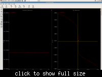
I am trying to simulate a sort of cmos inverter (see attached figures). For the same value of DC input in DC sweep and transient analysis, its output voltage is quite different, For eg if you see the attached waveform, the DC sweep shows that the output at 3.025mV should be around zero or more preciselly 35nV. And in the transient analysis when I put 3.025mV at the input, I get -46mV at the output I can't find the problem.
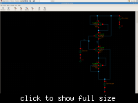
 

This is expected generally, actually the DC sweep simulations do not include analysis of capacitors (They do include their parasitics if available in model.). But in transient simulation those capacitors are empty then in time they charge. Looking at DC solution you cannot say that the DC solution is the only possible solution for complicated models of MOSFETs. So what I suggest is that you extract the exact value of output voltage (As exact as your absolute tolerance allows.) then force your output to that voltage, then disconnect your output from that voltage see if it holds true.

But this measurement is kind of obsolote for an inverter as you wouldn't want to use inverter at that point. As an open loop system with high gain the 46 mV error is actually a good match between DC sweep and transient. Also a better way to look at the zero crossing point of an inverter is to connect its input to the output. If you do this and apply this voltage to the input of an exactly same inverter across a voltage controlled voltage source you can get better results.
 

Status
Not open for further replies.

Part and Inventory Search

Welcome to EDABoard.com

Sponsor

Back
Top