d123
Advanced Member level 5

Hi,
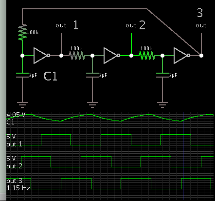
The following circuit to delay a clock signal appears on a few forum discussions (can't find them now after re-searching, so unable to post the links):

It works in a simulator, with a little tweaking, but didn't work on a breadboard at 2Hz, 3, 16, 32, 64, etc., up to 16.7kHz, and changing passive components to fit frequencies, until I connected the NOR gates as inverters (which possibly makes the NOR gates fairly redundant for my application if the same can be achieved with NOTs):

The above one was with first-order highpass filters instead of the first-order lowpass, but neither worked as the original schematic and simulation show it should.
Why might that be?
I looked with my bottom-of-the-range oscilloscope and it's 1 channel, and the signals out of delay#1, delay #2 and delay#3 are all suitable squarewaves that go from 0V to +5V, +4.2V, +4.2V, respectively (slight difference in width of mark/space between them, obviously), with NOR inputs tied together; but the circuit flatlines out of delay block #1 and onwards if connected as original circuit shows. It makes sense to me that the NOR never has 00 at either point of the switching because of the resistor or capacitor to ground from the delay (filters) - is it something to do with that?
The intention was to look into delaying a pulse for RGB LEDS, to blend them - but also have each colour visible at a point in the cycle, but as the result is horrible to look at (low speed and high speed) and I suspect would kill off my tomato seedlings or genetically harm them, it is not something I would use on a plant.
This was the intention, and what I got on a breadboard from the second schematic:

This seems yet another useful building block to understand enough to implement reasonably well for hobby circuits as it looks useful for some things, that is a reason for interest in speculation as to why not functioning properly. Thanks.
The following circuit to delay a clock signal appears on a few forum discussions (can't find them now after re-searching, so unable to post the links):
It works in a simulator, with a little tweaking, but didn't work on a breadboard at 2Hz, 3, 16, 32, 64, etc., up to 16.7kHz, and changing passive components to fit frequencies, until I connected the NOR gates as inverters (which possibly makes the NOR gates fairly redundant for my application if the same can be achieved with NOTs):
The above one was with first-order highpass filters instead of the first-order lowpass, but neither worked as the original schematic and simulation show it should.
Why might that be?
I looked with my bottom-of-the-range oscilloscope and it's 1 channel, and the signals out of delay#1, delay #2 and delay#3 are all suitable squarewaves that go from 0V to +5V, +4.2V, +4.2V, respectively (slight difference in width of mark/space between them, obviously), with NOR inputs tied together; but the circuit flatlines out of delay block #1 and onwards if connected as original circuit shows. It makes sense to me that the NOR never has 00 at either point of the switching because of the resistor or capacitor to ground from the delay (filters) - is it something to do with that?
The intention was to look into delaying a pulse for RGB LEDS, to blend them - but also have each colour visible at a point in the cycle, but as the result is horrible to look at (low speed and high speed) and I suspect would kill off my tomato seedlings or genetically harm them, it is not something I would use on a plant.
This was the intention, and what I got on a breadboard from the second schematic:
This seems yet another useful building block to understand enough to implement reasonably well for hobby circuits as it looks useful for some things, that is a reason for interest in speculation as to why not functioning properly. Thanks.