Vermes
Advanced Member level 4

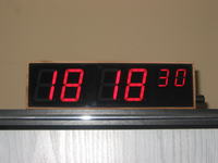
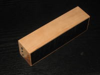
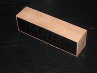
On the left side, the clock has buttons to control it and a DS18b20 temperature sensor, and on the right side - a supply input for an old nokia power supply.
LED display: 4x1.5'' and 2x0.8''
Housing: milled using CRC machine from a single piece of wood
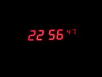
The main advantage is that the clock adjusts the light: at night it doesn't dazzle the eyes and at day it is light and readable.
The electronics are from: Kolejny zegarek LED na AtMega8, ale dokładny
Some information's about this clock can be found on the bottom of this thread.
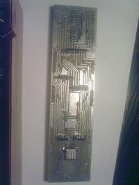
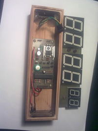
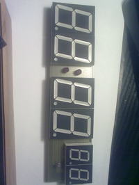
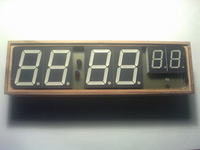
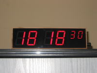
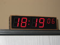
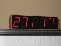
About the clock from the article:

This clock is based on a LED display and Atmega8. It displays only hours and minutes. It has an automatic backlight adjustment and a software correction of time. (just set correction on 0, wait a week, count the difference and set the correction).

Since the displays generate a 4V drop of voltage, an additional diode near the 7805 stabilizer was used for a small power boost. As the breakdown power supply a GoldCap capacitor (0,22F) was used. The rest of the circuit is cut out with a Schottky diode was used – 1N5817 (or 1N5819).
Signal on PC1 informs the driver that there is no mains, which results in switching off everything in the circuit except the counting of the time. In this state the circuit takes only 15uA therefore the GoldCaps capacity lasts for a long time – about 6 hours.
The processor works with a buit-in 2MHz generator, and the clock quartz 32,768MHz is connected to OSC1 and OSC2 inputs. It drives the Timer2 in asynchronous mode which generates a interruption in exact 1 second intervals.
A a tension divider with a photoresistor is connected to the PC0 (ADC0) input and the internal converter A/D measures the tension from the divider and adjusts the backlight of the display. The photoresistor is connected to +5,6V to not take power from the breakdown power supply capacitor. A 100nF capacitor is connected to the RESET input of the processor to increase the immunity. Instead of the SMD (BC807) transistors BC327 (0.8A 50V) can be used.
The whole circuit is powered from a Nokia mobile phone impulse charger (9V).

Link to original thread (of the primary clock) - Zegar pokojowy Atmega8