Vermes
Advanced Member level 4


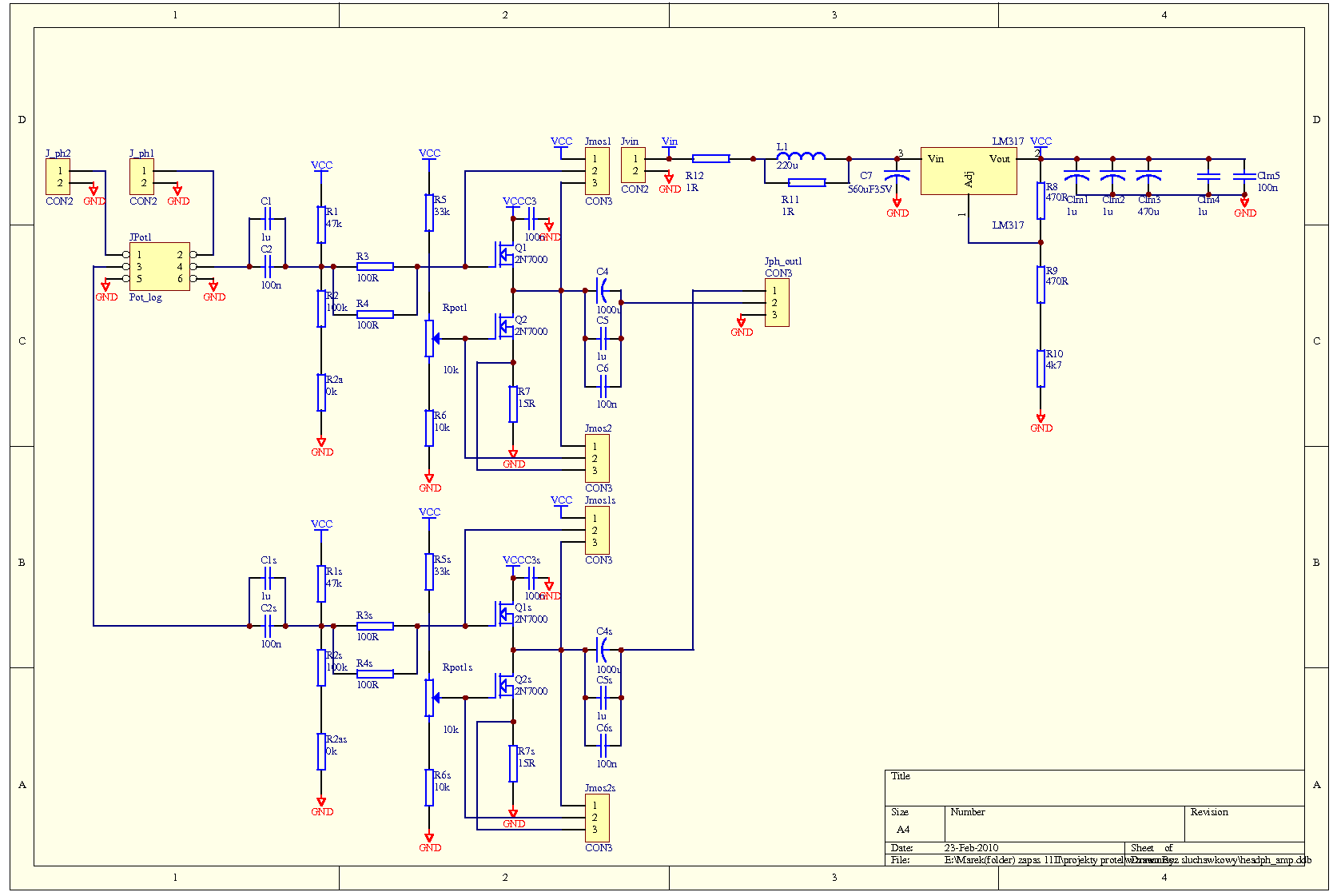
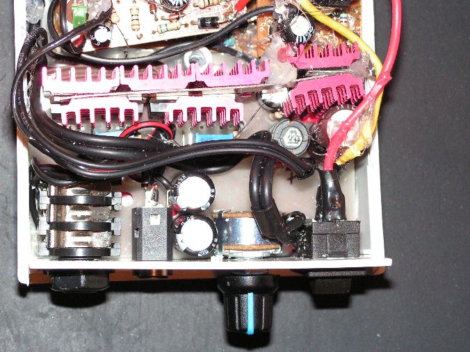
It is a cheap construction of a headphone amplifier AVT 2426 – very popular, with two MOSFET transistors per channel. Board is designed to easily test different kinds of transistors (with two different systems of legs), different values of resistors, different capacitances of capacitors. The board fits the Z5, Z5-J or similar housing along with the power supply.
 **broken link removed**
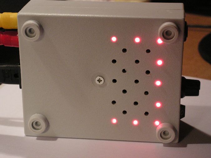
Power supply consists of four mobile phone chargers from Forever, processed by adding a diode 1N5817. At a small load, they give a total of 24-25V. To avoid problems with interference, RLC filter was applied before the stabilizer and few filtering capacitors in most important places of the board. 10Kohm stereo logarythmic potentiometer is used for the volume control. The PCB is one-sided, with four rings and small.
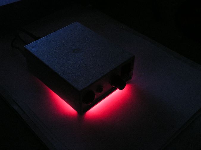
To prevent overheating. The amplifier has ventilation holes in the bottom side of the housing, in free space on the board, so air can flow, and in the back of the housing. After closing, the housing heats up significantly, but it can operate in such temperatures. When drilling holes, you can put diodes which are used for lighting and provide nice look of the device.
Transistors used are four STP60NF06 – their parameters make them perfect for controlling DC motors, but at high current, at which linear characteristic begins. Quiescent current was set to 100mA (linear characteristic begins at 15A). Then heat sinks were assembled and the whole device put in the housing.
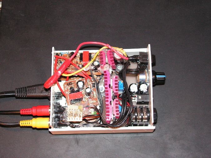
The housing was filled quite well (what unfortunately increases the temperature inside).
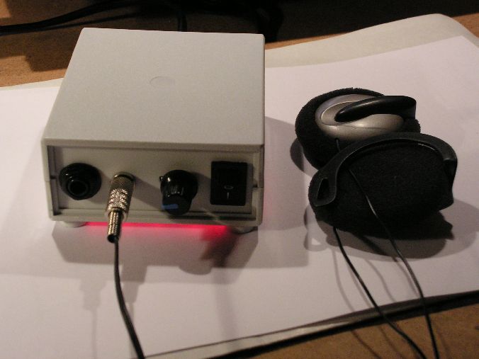
The amplifier was tested on Koss headphones KSC7 (32ohm) **broken link removed**.
There were three signal sources:
- IBM laptop T41 – sound was louder and nicer
- Sansa e260 – hard to tell the difference
- Philips Expanium discman – as above
Conclusions:
Supply from pulse power supply:
It operates well, right filter and you do not have to worry about the interference. 1R resistor was used, 220uH coil and 560uF capacitor and then additional resistors, 20ohm 1,25W in total in series, so they give some of the heat in different place of the housing. The most important thing is that the voltage filtering on amplifier's blocks should be appropriate. This is provided by additional capacitors 1uF, but thanks to holes on the PCB, you can solder even larger capacitors. Resistor connected in parallel to the inductance is used to stop the surges on it, so in the case of a sudden disconnection from the power, there was no negative voltage on the capacitor. EM interference is not a problem – the signal cables are coaxial, thus „self-shielding”, there are many small capacitors and a lot of ground.
Small housing:
Transistors withstand up to 175 degrees Celsius, LM317 turns off at much smaller temperature. Temperature does not affect the quality of sound – the change of MOSFET resistance is too small.
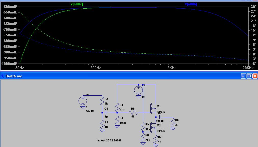
Resistance values on „upper” transistor:
Initially it was to be 100k and 200k in total, because it positively affects the characteristics, which can be seen on graphs from Space. Unfortunately, that did not operated properly.

Transistor:
The device should operate on any transistor. But if you want to use linear part of characteristic, you should choose transistors with maximum current of 5-10A (such as BUZ72A – linear from 1,5A) or even lower (but higher than 150-200mA and even 500mA, transistors for 120mA break).
Elements used:
- potentiometer
- knob
- housing Z5-J
- small jack socket
- big jack socket
- switch
- 2x cinch socket
- supply socket
- 4x STP60NF06
- LM317
- 14x heat sink
- 2x potentiometer 25 rotations 100k
- 4x power supply
- 9x LED
- capacitors
- resistors
Link to original thread (useful attachment) – Wzmacniacz słuchawkowy klasy A AVT 2464
