Vermes
Advanced Member level 4

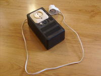
It is an useful device for everyone who is not fully satisfied with self-assembly kit for AVT-721, which, unfortunately, does not react to a single clap or a similar sound. Just that something falls on the floor and the light is off. Also unnecessary lighting fluorescent lamps during the day shortens their lifespan.
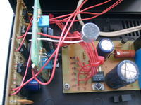
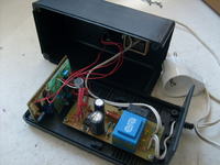
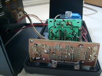
Assumptions:
- the system is to respond to two clapping at a certain time interval
- use the AVT-721 kit and not make major changes to it despite desoldering something
- the system is to be digital – some counters, flip-flops and TTL gates
- no CPU to turn on and off the lights
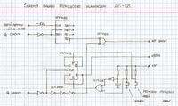

After powering the supply, its output is off and red diode “standby” is lit. First clap results in turning on the green diode and switching to the “ready to switch” mode. Second clap (1,5-4sec after the first one), switches the output states (to the opposite state) and the device to the standby mode which is indicated by the red diode. If there is silent after the first clap, the device will switch to the standby mode after approximately 4sec, with no changes to the output state.
How it works
After powering, the counter 4017 is reset by capacitor C3. High state that switches the red diode appears at its output Q0. At the same time, JK flip-flop is reset (turned into a T flip-flop) so the system exit is in low state and the system NE555 begins to generate a signal with a frequency of about 2Hz.
First clap is counted by the counter 4017, so high state appears at its output Q1. The clap loads the capacitor C4, which is responsible for 1,5sec “stunning” of the system.
High state of the output Q1 is negated, and as low state after the negator it allows counting the impulses from the NE555 generator by the counter UCY7493. The counter operates in a binary system, so until after the eighth impulse there is high state at the output QD. It passes through the EX-OR gate and resets the counter 4017 – the system returns to the state it was after power.
However, before the system counts to eight, the clapper manages to regain the sensitivity and hear the other clap. It will result in appearing high state at the output Q2 of the counter 4017, and thus the change of the T flip-flop – it changes the state to the opposite state with every impulse given at the “CLK” input). The signal from the output Q2 goes on through three negators (excess that introduce a tiny delay extending the CLK signal of the T flip-flop) and EX-OR gate to the input that resets the counter 4017. That is how the system returns to the standby mode after changes the output state.
JK flip-flop UCY7472 used here has an additional control inputs Set and Reset. The first of these can be connected to the button turning on the receiver without clapping, and the second one can be connected to the button which turns it off.
Link to original thread (useful attachment) – Klaskacz, czyli akustyczne zdalne sterowanie
Last edited:
