Continue to Site

Welcome to EDAboard.com

Welcome to our site! EDAboard.com is an international Electronics Discussion Forum focused on EDA software, circuits, schematics, books, theory, papers, asic, pld, 8051, DSP, Network, RF, Analog Design, PCB, Service Manuals... and a whole lot more! To participate you need to register. Registration is free. Click here to register now.

Chossing MOsfet for boost converter

Status
Not open for further replies.

lerameur

Junior Member level 1
Joined
Oct 19, 2006
Messages
19
Helped
0
Reputation
0
Reaction score
0
Trophy points
1,281
Activity points
1,454
Hello everyone,

I have a circuit with one 150watt mosfet
If I want to double the current load, is it better to parallel the mosfet ?
OR use a 300watt rated mosfet ?

Also dont get that a Mosfet can be rates at 150W or 300W or event 600W, and all thre have the same size and (TO 220)
Sure the heatsink need to be selected accordingly, It this a normal situation with mosfets in general?

ken
 

Switching devices placed in parallel, particularly if not belonging to the same manufacturing lot, it is expected to have discrepancies even though within the specified range, which means that it is not correct to assume that current will be equaly splitted among both, so I would prefer to choose a single Mosfet capable of dealing with a higher currernt.
 

Hi,

MOSFETs usually are not selected by Watts.
Thus it's not clear to me what you call a "150W MOSFET".
In the datasheet when you read about "Watts" then it usually is the maximum allowed power dissipation.

For a boost converter you usually don't want 150W (or higher) power dissipation.
You rather try to keep it as low as possible.

Klaus
 

Hi,

I'm afraid that this plan of doubling your load current might land you in trouble. First of all, there is a point of concern. How do you intend to double the load current?

MOSFETs are not selected in wattage but by peak drain current and drain-to-source voltage.

To be able to get help, you have to list the specification of your converter, like Vin, Vout, frequency, duty cycle, mode of conduction, peak inductor current, and so on.
 

Hi,

MOSFETs usually are not selected by Watts.
Thus it's not clear to me what you call a "150W MOSFET".
In the datasheet when you read about "Watts" then it usually is the maximum allowed power dissipation.

For a boost converter you usually don't want 150W (or higher) power dissipation.
You rather try to keep it as low as possible.

Klaus

Hello

I am posting a circuit, the output is at 24 v and about 15 amp so about 360 watt power output.
Now I have a load of 1050 watt same voltage. I thought of just trippling the mosfets and tripling the transformer size.
Or just use the equivalent 1050 watt min mosfet power dissipation.

Ken
 

Hi,

This 24V x 15A = 360W is power supply output power.
You will never find this value in a Mosfet's datasheet.

A boost converter is a switching power supply. The Mosfet switcges ON and OFF with high frequencyand varying duty cycle.
The power loss is mainly
* switching loss (during each switch transition, it depends alittle on output current, but not that much)
* and conductive loss ( when the Mosfet is ON, caused by the drain current. It depends on load current and duty cycle)
For a good 360W output boost regulator the power dissipation in the Mosfet should be less than 30W.

Doubling the Mosfets won't work. Not only because the gate drive signal will become slower, mainly because the inductor will come into saturation. Causing high currents ... something will get damaged...PCB, inductor, Mosfets, diodes...who knows...

Buy a power supply rated for your load.

Klaus
 

look up ON resistance of mosfet at 80 deg C say, multiply this by the RMS current in the fet - squared - i.e. I^2 x R

then try to estimate the turn off losses and turn on losses - add these 3 to get the power dissipated in the mosfet, hopefully less than 10W for a TO-220.

Then size a heatsink to give < 100 deg C junction on the mosfet, with the calculated dissipation, say 10W, in this case, for 20C ambient 80degC/10watt = 8 degC per watt - most heatsink catalogs have this number on their parts ...

good luck ...
 

The question is rather like asking "if I fit two engines to my car will it go twice as fast?"
The answer depends on so many other factors it is impossible to answer but the gut feeling is you need to do a lot more than doubling up on switching capacity, you really need to do a complete redesign.

Brian.
 

Consider interleaving two or more boost converters. By staggering On-times, it lets you operate additional mosfets yet stay within limits.
 

Consider interleaving two or more boost converters. By staggering On-times, it lets you operate additional mosfets yet stay within limits.

I am going to redesign according to tl494 datasheet.
 

Brian's analogy is golden. :thumbsup::thumbsup:

Every car tuner knows that once that you increase the engine power past certain limit, there will be many things that require upgrades.

From the transmission, to the suspension, to the brakes, tires and everything in between.
And individually, the engine itself may require a larger radiator and cooling fan, electrical oil pumps and coolers, and so forth.

In some instance, all that is left from the "stock" car is the sheetmetal.
 

I am posting a circuit, the output is at 24 v and about 15 amp so about 360 watt power output.

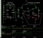
Is your initial power source 12V? If so then the step-up ratio is 2 which leads to the option of a voltage doubler based on capacitors.

555 bias H-bridge 12V 2-cap doubler load 0_8 ohm gets 23V.png

This simulation demonstrates a concept. Components need to endure tens of Amperes. Gangs of capacitors would be needed. Mosfets can be substituted for transistors.
 

Status
Not open for further replies.

Similar threads

Part and Inventory Search

Welcome to EDABoard.com

Sponsor

Back
Top