Continue to Site

Welcome to EDAboard.com

Welcome to our site! EDAboard.com is an international Electronics Discussion Forum focused on EDA software, circuits, schematics, books, theory, papers, asic, pld, 8051, DSP, Network, RF, Analog Design, PCB, Service Manuals... and a whole lot more! To participate you need to register. Registration is free. Click here to register now.

Cheap ATxmega programmer, or PDI handling in USBasp

Status
Not open for further replies.

Vermes

Advanced Member level 4
Joined
Aug 2, 2011
Messages
1,163
Helped
0
Reputation
0
Reaction score
0
Trophy points
1,316
Activity points
22,318


Atxmega has many advantages in comparison to AVR. It is faster (32MHz), has more peripherals (5 UARTs, 16 PWM channels) and module construction.

It is easy to implement a new protocol for programming in USBasp. PDI requires a constant clock signal and it disconnects wher the frequency drops below 10kHz. Time requirements of that type are problematic for V-USB (USB implementation used in USBasp), because the USB transmission is handled by software and cannot do anything else in that time.
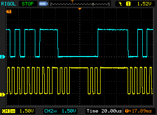
8656737200_1345075645.png


Picture above presents gaps in the clock signal caused by interruptions of V-USB.

Interruption for handling a simple transfer of control type takes only 40-50us and it is enough not to interrupt the PDI connection handled by software. Sending greater number of data at once interferes with the clock, but you can cope with that when you organize the work of the programmer, so that it collects the data and use them in the moment when there is no transmission.

Presented here implementation switches to the clock generation by timer for the time of USB transmission.
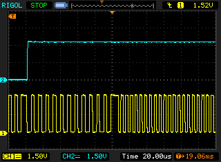
9360134100_1345075695.png


Picture shows on the left: software clock, on the right: clock from timer.

Physical connection:
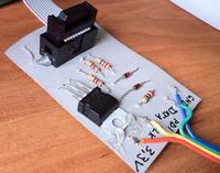


Standard USBaspis for 5V, and PDI of Atxmega operates at 3,3V, the simplest way to decrease the voltage is a Zener diode.


SCK controls PDI DATA and MOSI is PDI CLK. If you have USBasp operating at 3,3V, just connect it as a normal PDI:
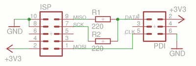
8962526200_1345075815.png


Power supply:
When you want to power the system from the programmer, add a 3,3V stabilizer to the 5V USBasp.

Software:
  • Firmware UABasp with PDI handling can be downloaded from
    HERE and patch uspasp-pdi-usbaspfirmware-20120816.txt (attachment)

    Unpack, add patch, compile:

    Code:
    tar xvzf usbasp.2011-05-28.tar.gz
    cd usbasp.2011-05-28/firmware
    patch <full/path/of/usbasp-pdi-usbaspfirmware-20120816.diff
    make main.hex

    and install it in the programmer.

    Note! Atmega48 is not supported, because there is no place for the additional code in the memory.
  • AVRDUDE with USBasp support and PDI:[/b]
    you need sources in version r1092 and patch usbasp-pdi-avrdude2091-20120816.txt (attachment)

    Code:
    svn co svn://svn.sv.gnu.org/avrdude/trunk -r 1092
    cd trunk/avrdude
    patch <full/path/of/usbasp-pdi-avrdude2091-20120816.diff
    ./bootstrap
    ./configure
    make
    *
    ./avrdude -C avrdude.conf -c usbasp -p x16a4 -U flash:w:../../../xmega/xmegatest.hex  -E noreset
    *
    avrdude: AVR device initialized and ready to accept instructions
    *
    Reading | ################################################## | 100% 0.02s
    *
    avrdude: Device signature = 0x1e9441
    avrdude: NOTE: Programmer supports page erase for Xmega devices.
             Each page will be erased before programming it, but no chip erase is performed.
             To disable page erases, specify the -D option; for a chip-erase, use the -e option.
    avrdude: reading input file "../../../xmega/xmegatest.hex"
    avrdude: input file ../../../xmega/xmegatest.hex auto detected as Intel Hex
    avrdude: writing flash (440 bytes):
    *
    Writing | ################################################## | 100% 0.29s
    *
    avrdude: 440 bytes of flash written
    avrdude: verifying flash memory against ../../../xmega/xmegatest.hex:
    avrdude: load data flash data from input file ../../../xmega/xmegatest.hex:
    avrdude: input file ../../../xmega/xmegatest.hex auto detected as Intel Hex
    avrdude: input file ../../../xmega/xmegatest.hex contains 440 bytes
    avrdude: reading on-chip flash data:
    *
    Reading | ################################################## | 100% 0.27s
    *
    avrdude: verifying ...
    avrdude: 440 bytes of flash verified
    *
    avrdude done.  Thank you.

Final effect – LED flashing:
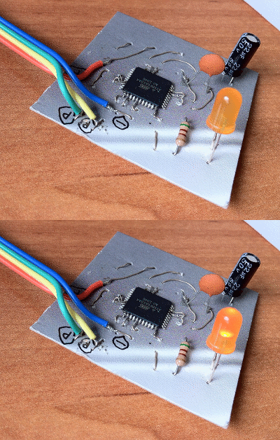
8935754800_1345075865.gif


Link to original thread (useful attachment) - Programator ATxmega za złotówkę, czyli obsługa PDI w USBASP
 

Hi

thanks from your post.

is it possible to attached HEX file for ATMega8? i can't make it!
 

Hi !
Thanks for your patches ! After a long and hard time, I managed to compile the usbasp firmware under Windows (atmel studio 6.0 installed to use avrdude and make). And to compile a patched avrdude (r1092) under Windows with MinGW.
It is working with my ATXMega64B3. But I'm not sure about the device configuration in avrdude.conf. I just copy and pasted a xmega definition and replaced the device signature. Can you tell me where I can find the others info ?

Regards,
Val'
 

After a long and hard time, I managed to compile the usbasp firmware under Windows (atmel studio 6.0 installed to use avrdude and make). And to compile a patched avrdude (r1092) under Windows with MinGW.

Hi Montspy

can you put your HEX file AVRDUDE and patch here? i couldn't do it myself!
 

Hi,
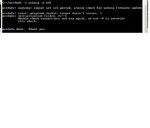
I noticed that I can only use my USBASP while plugged in my USB 3.0 ports. On USB 2.0 ports I get :
Code:
avrdude.exe: initialization failed, rc=-1
             Double check connections and try again, or use -F to override
             this check.
Same on a friend's PC. (It has no USB 3.0 ports).

Can you confirm ?

You can find attached the hex file for ATMega8 (patched), and the patched avrdude.

Regards,
Val'
 

Attachments

  • avrdude.zip
    2.2 MB · Views: 325
  • main_patched_atmega8_for_pdi.zip
    6.6 KB · Views: 321
Last edited:

thanks for your attach file.

i think "initialization failed, rc=-1" error is about connection between ATMega8 and target chip, this connection must be check :

SCK
MISO
MOSI
RST
Vcc
GND
 

Dear Montspy

i tested your HEX file and AVRDUDE with USB2.0 port and ATMega16 and ATXMega128A1.

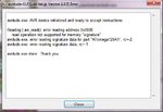
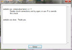
i can program ATMega16 without problem. but when i tried to program ATXMega128A1 i got below errors : (aatached image)

i think your AVRDUDE patch has an problem. what is your idea?
 

Attachments

  • err1.png
    err1.png
    53.3 KB · Views: 336
  • err2.png
    err2.png
    40.1 KB · Views: 322

More elegant way for connecting uC to programmer to keep uC pins in good shape :

**broken link removed**
(for this adapter use hot air SMD rework station)


or this little more expensive adapter :) :

**broken link removed**
 

thanks for your attach file.

i think "initialization failed, rc=-1" error is about connection between ATMega8 and target chip, this connection must be check :

SCK
MISO
MOSI
RST
Vcc
GND

No this is not the problem, with the same connections, it works on my USB 3.0 ports (Renesas Electronics controller), but not on my USB 2.0 ports (Intel 6 Series Chipset). I don't know why it could do that.

Dear Montspy

i tested your HEX file and AVRDUDE with USB2.0 port and ATMega16 and ATXMega128A1.

i can program ATMega16 without problem. but when i tried to program ATXMega128A1 i got below errors : (aatached image)

i think your AVRDUDE patch has an problem. what is your idea?

Exact same error. What is your USB 2.0 ports controller ? (Do you have USB 3.0 to test ? I know it's weird).

tpetar : My IC is solder on a custom made board with PDI standard 6 pins header. Then I have the adapter board (with the 2* 220 Ohm resistors). Every connection is solid (connectors and cables), no breadboard or anything. My connections are not the problem. I'll try to power the board from another 3.3V line than from the USPasp.

Val'
 

Exact same error. What is your USB 2.0 ports controller ? (Do you have USB 3.0 to test ? I know it's weird).

Unfortunately my PC hasn't USB3.0 port. i don't know my USB2.0 Ports controller! how can i understand it?
 

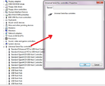
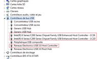
Go to Device Manager, you have something like USB bus controller. Open it, and you we'll see.

Val'
 

tpetar : My IC is solder on a custom made board with PDI standard 6 pins header. Then I have the adapter board (with the 2* 220 Ohm resistors). Every connection is solid (connectors and cables), no breadboard or anything. My connections are not the problem. I'll try to power the board from another 3.3V line than from the USPasp.

Val'


My post is linked with Vermes first post in thread. I post suggestion for uC socket adapter to maintain uC pins in good shape.

Regards,
Peter

:wink:
 

My post is linked with Vermes first post in thread. I post suggestion for uC socket adapter to maintain uC pins in good shape.

Regards,
Peter

:wink:

Ok, I did not get that :)

Powering the board via a USB and 3.3V regulator (not via the USBasp) does not change anything.

Vermes, what USB controller do you have on your PC ?

Val'
 

Go to Device Manager, you have something like USB bus controller. Open it, and you we'll see.

i do it,but it dose a white window only.
 

Attachments

  • p.png
    p.png
    65.1 KB · Views: 337

Here is what I get :


Have you tried with all your USB ports ?

Val'
 

Dear vermes,
I am really appreciate your hard work

I am bit beginner for avr as well as xmega
I have usbasp and tried to connect usbasp to atmega32 and I found following errors
please see the picture
usbasp.JPG

Please advice
 

Status
Not open for further replies.

Similar threads

Part and Inventory Search

Welcome to EDABoard.com

Sponsor

Back
Top