gres
Full Member level 4


It’s unfinished project of Lama V4 heli. The problem with that model is a diode that indicate low battery level, which is poorly visable. To have long fun with power package, you need to keep voltage limit per cell – about 3V. Diode is not always visable, especially at sunny day or heli is far away at the sky. That’s why sound signal is importand.
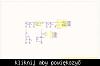
In hardware meaning system is very simple. Simple measure at divider by ADC in Attiny13A (firstly Attiny11). Depend on voltage level uC control sound alarm (or diode situated in “right” place)
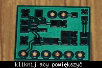
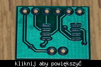
PCB has dimensions 15x17mm. As it was first version, device consist space for stood pin 2.54mm with program interface, and two soldering poles that allow to solder buzzer’s wire. Device could also consist slot for chargering/ balancig. It should be easy available at the shops
PCB is made by www.prototypy.com Laminat 0,8mm. as you can see at the bottom layer soldermask is slide a little, althought that I recommend that manufacture. Very good relationship between costs and quality.
Unfortunately I sold heli before I had installed.
I put all diagram (with frame).
Picture quality is low because converter PDFill is poor, and I don’t know better.


text comes from: https://www.elektroda.pl/rtvforum/v...rk=topic&sid=223084089edd5f1471d34986edb029fa