Vermes
Advanced Member level 4

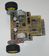
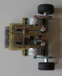
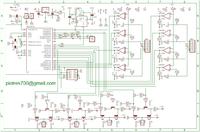
Linefollower was made in SMD technology – it is a prototype with first version of the software. The PCB and the schema can be self made. The main element of the robot is AVR microcontroller Atmega8 clocked by an external quartz 12MHz. Motors are controlled by keys based on MOSFET transistors. A motor is supported by 2 keys, 2 transistors each, what makes it possible to control both speed and the direction of motor rotation. Keys are taken from the manufacturer's note of Atmel describing a BDCM motor controller. 4 reflective sensors CNY70 were applied as the optical sensor. The sensors are connected to the comparators constructed on the basis of a LM339. On the PCB there are two LM339 chips each with 4 comparators. 2 SMD potentiometers are used as reference voltage divider for the comparator. On the PCB there is a place for RRFQ1-XXX receiver and soldering the antenna socket which is another alternative for the construction as a remote-controlled robot. The PCB contains a socket compatible with most AVR programmers STK XXX class. Power supply consists of 2 batteries from a phone. The drive is made of 2 motors from CD-ROM that are responsible for tray entry/exit. Lego wheels turned into metal, independent axes are driven by belt connection (rubber band). The PCB is the skeleton of this construction.
The charge for Atmega was written in C in AVR Studio 4 compiler.
The robot's dimensions: 12x9cm.
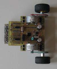
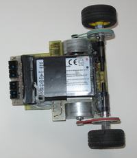
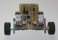
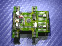
The scheme, PCB – mirror reflection, distribution of elements, rendering of the board and several photos of assembled robot:
Link to original thread (useful attachment) – CENTURIO - Linefollower