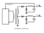
Center tapped transformer (forward converter)
- Thread starter kathmandu
- Start date
- Status
- Not open for further replies.
kathmandu
Full Member level 5

I think it's all about the (lack of) cross-regulation when you deal with multiple/unballanced outputs.
I'll try to get some help on this particular thread: Fundamental physics of coupled inductor cross-regulation in forward converter?.
I'll try to get some help on this particular thread: Fundamental physics of coupled inductor cross-regulation in forward converter?.
std_match
Advanced Member level 4

Do you have any load on the +12V output?
With no load, overshoots and ringings can be rectified by the diode and increase the output voltage.
With no load, overshoots and ringings can be rectified by the diode and increase the output voltage.

- Joined
- Jan 22, 2008
- Messages
- 53,719
- Helped
- 14,812
- Reputation
- 29,921
- Reaction score
- 14,447
- Trophy points
- 1,393
- Location
- Bochum, Germany
- Activity points
- 303,688
Apart from possible ringing and overshoot, a forward converter shows only tracking outputs if both inductors are in continuous conducting mode (CCM).
To achieve tracking over a wide output load range, you better go for flyback converter.
To achieve tracking over a wide output load range, you better go for flyback converter.
kathmandu
Full Member level 5
I had a 60W load on the 24V output and a smaller one (2W) on the 12V one. If I increase the load (20W) on the 12V output, the voltage is decreasing (16V), indeed, but I don't want such a big load on the 12V rail (it's mainly for housekeeping and some 12V relays).
I've read about using a coupled output inductors and I've ran few tests. The 12V rail is reaching 16V on a smaller load (1-2W) but it's highly unstable (if the load on the 24V rail is changing).
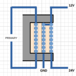
Anyway, I have no informations about the coupling technique (like the two inductors turns ratio, by example). As the unloaded output voltage (12V) is half of the main one (24V), maybe one inductor needs to have more/less turns (double/half) or any other particular ratio, based on load current distribution?
As far as I have read, the coupled inductors work as a regular transformer, keeping an induced voltage across the unloaded inductor to further avoid the overcharging of the output capacitor. Am I wrong?
- - - Updated - - -
@FvM:
Many thanks for your comments! Anyway, I'll stay with the forward topology as it presents some advantages (continuous output current/low ripple, lower switch peak current, a smaller transformer and so on). In this particular situation, I guess I'll go for a series voltage regulator on the 12V rail.
I still have another question though: was it a good idea to use a tapped output instead of a separate winding for the 12V rail (regarding cross-regulation)?
BTW, what about the weighted resistor feedback? Will it ruin both output regulations?
Last edited:
Easy peasy
Advanced Member level 6
for such mismatched loads - the proposed ckt is not such a good idea ... buck ckt off the 24V to derive the 12v would be better ...
kathmandu
Full Member level 5
Never thought of this kind of troubles (my first unbalanced forward converter).. lesson learned.
Anyway, I've just found some literature about "the coupled-inductor in a multiple-output forward-type converter".. maybe I'll give it one more chance.
Anyway, I've just found some literature about "the coupled-inductor in a multiple-output forward-type converter".. maybe I'll give it one more chance.
- Joined
- Jan 22, 2008
- Messages
- 53,719
- Helped
- 14,812
- Reputation
- 29,921
- Reaction score
- 14,447
- Trophy points
- 1,393
- Location
- Bochum, Germany
- Activity points
- 303,688
You can try to make the 12 V inductor large enough to provide continuous current at 2 W load.
Coupled inductors can basically work, obviously the inductor turns must have the same ratio as the transformer windings (2:1).
For the given load ratio 60W:2W, a linear 12V voltage would be the most simple solution. Or small buck, as suggested by Easy peasy.
Coupled inductors can basically work, obviously the inductor turns must have the same ratio as the transformer windings (2:1).
For the given load ratio 60W:2W, a linear 12V voltage would be the most simple solution. Or small buck, as suggested by Easy peasy.
kathmandu
Full Member level 5
I have decided to go with a series regulator for that 12V (housekeeping) output.
Anyway, I thought about other simple ways to actually regulate this kind of unloaded outputs and something like this crossed my mind:

It is some kind of controlled rectifier. Is it going to work? (from the efficiency point of view as I don't need any tight voltage regulation).
Anyway, I thought about other simple ways to actually regulate this kind of unloaded outputs and something like this crossed my mind:
It is some kind of controlled rectifier. Is it going to work? (from the efficiency point of view as I don't need any tight voltage regulation).
Easy peasy
Advanced Member level 6
it is a discrete buck switcher - not a partic good one but may suffice for low power, see also NCP3064 ( i think ) for an easy buck switcher with current limit
- - - Updated - - -
also MC34063A ( from the original device maker )
- - - Updated - - -
also MC34063A ( from the original device maker )
kathmandu
Full Member level 5
You're right, there are tons of integrated solutions (the well-known LM2596 having internal current limiter and a very convenient TO-220 package) but I was just thinking of a discrete, cheap and low footprint concept. Just for the reference, do you know of any other simple (discrete) solutions?
Easy peasy
Advanced Member level 6
For 2W on the 12V rail - its hard to beat the MC34063A - and its pretty cheap - remember you still need the diodes to rectify the Tx wdg and a choke and a cap to form the raw voltage - missing from your post#9 above
Easy peasy
Advanced Member level 6
the xtor E-B will zener at approx 6V in reverse when the winding goes negative ... and thus there will be current flow in the buck diode and the wrong way through the main xtor ...
Easy peasy
Advanced Member level 6
2nd way is flawed too - look closely at what other E-B can be zenered ...
kathmandu
Full Member level 5
Easy peasy
Advanced Member level 6
unfortunately there is a small chance (load dependent) that your ckt could end up operating in a linear mode and cook the series pass xtor ...
T
treez
Guest
RT6208 buck for the 12v output.
In current mode forward, you need coupled inductors for good cross reg...but with your load difference, buck is best.............i find everywhere i work insist on loads of rails out of a single transformer...it just doesnt work really.....unless they are all highly loaded all the time....evn then its not great and needs coupled inductors if current mode forward.
Ill send you TI app note on it.
see point 5 on the 3rd page of the attached
Attachments
- Status
- Not open for further replies.
Similar threads
-
-
-
-
Kapton (25um) gapped Two Transistor Forward transformer?
- Started by cupoftea
- Replies: 0
-
Gate Drive transformer for Two Transistor Forward SMPS.
- Started by cupoftea
- Replies: 1


