Vermes
Advanced Member level 4

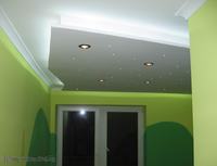
This project can be a part of architecture of lights in the house. Nowadays the energy saving target is really important, so the light was based on LEDs in various forms. They are LED “bulbs” in the housings for typical ceiling halogen holders (230V supply), strips of SMD LEDs and classic diodes in the housings for thread mounting. The system was divided into 3 modules: two executive systems and a controller based on the Atmega162 microcontroller. The controller allows you to light sequentially up to 12 halogen lamps 230V (using the executive system with triacs), regulates the brightness of the LED strip 12V and simulates the sky with stars in the form of 40 blue LEDs operating in 8 independent channels. Starry sky can operate in different modes of animation, and the substantial resources of the microcontroller program memory (16kB) allow you to make almost any passage of light. The program in its basic version is not even half the available space, so it can be developed. The controller support is possible by remote control RC5 or four classic flush-mounted switches. The system provides automatic turning off the lights after a break and return to the power supply.
Flowchart:
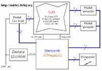
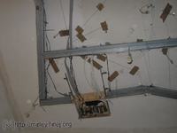
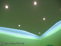
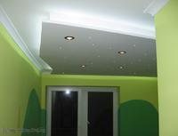
The most problematic thing to make is the suspended ceiling with LEDs and halogen lamps. The model project uses 10 halogen lamps, 40 blue (stars) and 6 white diodes (placed in one line) in the hole housings and 10 meters of strip with SMD diodes in white. LED strips are controlled by the executive system built in the controller. The same is with 6 white LEDs. Halogen lamps are controlled by the executive system of 12 triacs (the system can be upgraded with two additional lamps). Two executive modules connected in parallel with the controller are used to control the blue LEDs (stars). Each of them can control up to 32 LEDs, however, in the model project one module controls 24 and the other – 16 diodes due to the size of the ceiling. Flush-mounted switches are connected directly to the controller, shorting its appropriate output to the mass. Power supply is connected to the system permanently by 12V/60W AC (inverter), the controller works all the time, so at any time the lamps can be turned on by remote control.
Schematic diagram of the controller:
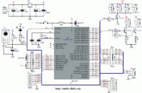
The main element of the system is microcontroller U1 (Atmega162) with the quartz resonator X1 (16MHz) and capacitors C1-C2 (22pF). Capacitor C7 (100nF) placed near the microcontroller, filters its supply. Resistor R1 (10k) pulls the RESET pin of the microcontroller to +5V, and the R switch (uSwitch) allows to reset it. Supply U1 is realized by stabilizer U2 (7805) and capacitors C3 (220uF), C4 (100nF), C5 (47uF) and C6 (100nF), which are necessary for proper operation of the stabilizer. LED D1 indicates pressing the remote control button (RC5 broadcast receive), its current is limited by the resistor R3 (470R). Circuit U3 (TSOP1736) is the IR chip receiver operating at a frequency of 36KHz signal. The supply voltage is filtered by the elements R2 (220R) and C8 (100uF). Connector FD1 (FD16) allows you to connect two executive modules (in parallel on one tape) to LEDs control that act as the stars. Screw connector P (ARK) is connected to the control cable of the wall switches and to LED mounted in the switch. The model project uses to control two double flush switches in which LEDs were mounted. These LEDs inform about turning off all light sources and allow you to locate the switch in the dark.
Transistor T1 (IRF1405) is an executive element to realized software PWM for LED strips 12V (light outline around the ceiling). This transistor will not heat up without a heat sink even at currents of several A due to the negligible resistance in the open state. Resistor R8 (10k) provides protection against accidental short-circuiting of the transistor's gate to +12V or mass, which can happen when you run the system. This resistor can be replaced with a jumper in the final layout. The LED strips fragments should be connected to the sockets GP1-GP4 (GW-02). In the model project for each of the connectors there were attached about 2-3 meters of LED strip (a total of 10m).
Transistor T2 (BC547B) with the resistors R6 (2,2k), R4 (1k) and connector GP9 (GW-02) is an output circuit to power the LEDs in the housing for hole mounting (FD1 is connected to eight more such systems). 1-3 diodes can be connected in series to GP9 connector. Diode current is limited by resistor R4, and with this configuration (degenerate emitter) regardless of the number of LEDs and fluctuations of the power supply, the current of LEDs will always be constant. In this case, the value of this current is set at about 4,3mA (4,3V at the emitter and 1k resistor value). Resistor R6 limits the base current of transistor T2. Elements T2 (BC547B), R7 (2,2k), R5 (1k) and connector GP10 (GW-02) are second identical, parallel working control channel. It allows you to connect more 1-3 LEDs.
Connector FD2 (FD16) allows you to connect the executive module with 12 triacs, that in turn provide appropriate turning on the halogen bulbs. Socket RS232 (GD-03), which is an UART output of the processor, allows you to use the serial port, if you need. The model project does not use this option. Prog connector (header) allows you to program the processor.
Schematic of executive module “stars” :
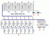
The system consists of 8 current sources built on transistors T1-T8 (BC547) and resistors R1-R8 (1k). Resistors R9-R16 (2,2k) limit the power of the transistors bases. The connection to the microcontroller in the controller is achieved by the connector FD1 (FD16). Operation of the systems with transistors T1-T8 is very simple: the high state on the base of transistor T1 (5V, because the microcontroller is powered by such a voltage) causes current flow in the base emitter connector of the transistor. A voltage within 4,3V (voltage drop on the base emitter connector is about 0,7V) on the resistor R1, so the current flowing through the resistor will be about 4,3mA. The same current will flow through the LEDs connected in series. LEDs (max 4 in series) will be attached to the sockets FD2-FD5 (FD16), but not all sockets must be used. If in each channel will work fewer LEDs, in the other connectors pairs of pins 1 with 2, 3 with 4 etc. should be shorted, to obtain a closed circuit for the flowing current. Application of the system with transistors T1-T8 allowed to bypass the problem of voltage fluctuations. Current, and thus the brightness, depends only on the resistors R1-R8. Note that the module supply voltage (VCC) must be sufficiently high, at least about 5-6V greater than the sum of the voltages of diodes conduction. If this condition is not met, the circuit with transistors T1-T8 will not work completely correctly, and the LEDs current will be less than it results of the applied emitter resistor. To power 12-12,3V as in the model project, you can use 2, maximum 3 blue LEDs, and for 3 blue LEDs and power of 12V the system works at the border and the current is slightly smaller than it should be. For the red and green LEDs the situation is slightly better due to lower conduction voltage. As a result, in some cases, you will need to supply LEDs by a higher voltage, and thus they cannot be attached to the point VCC, which in normal conditions will be on the potential of 12V relative to the mass. This fact is related to the LEDs strip powered by 12V, which is used in the project. It determines the power amount of other parts of the system. Capacitors C1-C2 (100uF) filter the supply voltage.
For the proper work of the system, you will need the executive module with triack, which can be found at uklad_wykonawczy.
Construction:
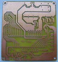
Installation of the controller should begin with soldering two jumpers. Assembly drawing will provide some help. Then, it is good to solder the smallest elements: resistors, quartz and its capacitors. Next, stand for the microcontroller should be mounted. The order of the other elements is negligible, but it is good to leave the connector for the end. Elements D1 and U3 should have long pins, so they can be easily mounted in the housing. Stabilizer U2 should be equipped with a small heat sink. Keeping in mind that all will be closed in the housing above the suspended ceiling, you should take care of cooling the stabilizer.
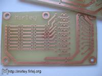
The executive module for the stars is also easy to install, there is no jumper on the board and you should start the soldering with the resistors. Then you should take care of transistors and filtering capacitors. At the end you should install the IDC connectors. No need to install all of them, it depends on the number of LEDs. Unused sockets should be replaced with jumpers (pin1 with 2, 3 with 4 etc.), since the LEDs are connected in series. The absence of one will prevent the operation of the entire series. The LEDs should be connected properly. Connector in the executive module allows you to connect 16 wire ribbon, which should be divided into 8 parts with 8 wires each. Pins 1-2 are to be connected to the first diode, 3-4 to the second etc. Odd pins are the anodes of diodes, ans paired – the cathode.
Tapes between the controller and the executive modules must be tightened 1:1, what means that the pins 1, 2, 3 … should hit the pins with the same numbers in the second connector.
The model system is powered from a 12V 60W switching power supply designed for use with LEDs. It is not a requirement and you can use the classic power supply with a transformer. Adequate current capacity is important to remember, which in the long LED strip will have to be of several A.
Using the converter as the power supply you have to remember to connect it to the grounding. Failure to do this will result in that on the output of the converter there will be alternating component with the value of 110-120V, which at the extreme cases can be dangerous. Alternating component on the low voltage output causes also another parasitic effect. When the LEDs are off (the controller cuts off all the control transistors) and are connected only from the 12V, the alternating component is rectified on LEDs, causing a small current flow, and thus makes all the LEDs light (very poorly, the effect is visible in total darkness). If the grounding connection will not eliminate this effect, measure the AC voltage on the low voltage supply mass relative to zero in the grid. You may find that after all it amounts to tens of volts. Just short the mass of the system to zero in the grid (or for better grounding, if available) through the resistor 47-100k.
The program for the microcontroller was written in Bascom.
Gallery:
Link to original thread (useful attachment) – Sterownik Podświetlania Sufitu