Continue to Site

Welcome to EDAboard.com

Welcome to our site! EDAboard.com is an international Electronics Discussion Forum focused on EDA software, circuits, schematics, books, theory, papers, asic, pld, 8051, DSP, Network, RF, Analog Design, PCB, Service Manuals... and a whole lot more! To participate you need to register. Registration is free. Click here to register now.

CCP Module of PIC18F4620 incrementing with Timer1

Status
Not open for further replies.

Neyolight

Full Member level 5
Full Member level 5
Joined
Aug 29, 2011
Messages
306
Helped
3
Reputation
6
Reaction score
3
Trophy points
1,298
Location
World
Activity points
3,624
Hi all

Im trying to use CCP module and timer 1 to capture frequency at RC2.

From the PIC18f4620 spec:

Capture Mode
In Capture mode, CCPRxH:CCPRxL captures the 16-bit value of the TMR1 register when an
event occurs on pin CCPx. An event is defined as:
• Every falling edge
• Every rising edge
• Every 4th rising edge
• Every 16th rising edge


But when I debug my code, I see CCPR1H and CCPR1L incrementing with Timer 1. What could I be doing wrong?
 

can u post your code so we can see what you have done?
 

Hello there.

I was working with CCP a long time ago and I dont seem to have the code with me anymore. What I do remember is that CCP didnt work for me AT ALL and I could not find why.
 

It's difficult to debug nonexistent code, the problem could have been due to several issues.

I would suggest try a few examples, like the following:

Code:
void main (void)
{
     unsigned int period;
     TRISCbits.TRISC2 = 1; /* configure CCP1 pin for input */
     T3CON = 0x81; /* use Timer1 as the time base for CCP1 capture */
     PIE1bits.CCP1IE = 0; /* disable CCP1 capture interrupt */
     PIR1bits.CCP1IF = 0; /* clear the CCP1IF flag */
     T1CON = 0x81; /* enable 16-bit Timer1, prescaler set to 1 */
     CCP1CON = 0x05; /* capture on every rising edge */

     while (!(PIR1bits.CCP1IF)); /* wait for 1st rising edge */

     PIR1bits.CCP1IF = 0;
     period = CCPR1; /* save the first edge (CCPR1 is accessed as a 16-bit value) */

     while (!(PIR1bits.CCP1IF)); /* wait for the 2nd rising edge */
     CCP1CON = 0x00; /* disable CCP1 capture */
     period = CCPR1 - period;
}

Chapter 8: Timers and CCP Modules

Build A Digital Tachometer/RPM Counter


BigDog
 

Allright since we started talking about CCP , Im back on it. This time I am trying to find the gap between two sqare waves ( pdf with an image attached).

Input : 12 V Square wave at RC2 ( CCP1 pin) of no set frequency

Methodology:
1) Set CCP to capture falling edge
2) Capture falling edge and save the value of timer 1 to t1
3) Set CCP to capture rising edge
4) Capture rising edge and save the value of timer 1 to t2
5) Gap = t1-t2

Code:
#include <p18f4620.h>
#include <usart.h>


#pragma config DEBUG=OFF
#pragma config OSC=INTIO7
#pragma config WDT=OFF
#pragma config LVP=OFF
#pragma config PWRT=OFF
#pragma config MCLRE=ON

void main (void)
{
	unsigned int t1;
	unsigned int t2;
	unsigned int Gap;
	char str[25];
	
	//Clock Setup
	OSCCON = 0b01110000; //select 8 MHz clock
	OSCTUNE |= 0b01000000; //Fosc = 32 Mhz
	
	TRISCbits.TRISC2 = 1 ; // Configure CCP1 pin as input
	T3CON = 0x81; //User Timer 1 as base timer
	PIE1bits.CCP1IE = 0; //Disable CCP1 capture interrupt
	PIR1bits.CCP1IF = 0; //Clear CCP1IF flag
	T1CON = 0x81;
	TMR1H = 0x00;
	TMR1L = 0x00;
	
	// USART 9600 8-N-1
	OpenUSART (USART_TX_INT_OFF & USART_RX_INT_OFF & USART_ASYNCH_MODE & USART_EIGHT_BIT & USART_CONT_RX & USART_BRGH_LOW, 51); // Baud Rate = 9600, 51
	
	
	while(1) {
	CCP1CON = 0b00000100 ; //Capture falling edge
	while (!(PIR1bits.CCP1IF)); //Wait for 1st falling edge
	PIR1bits.CCP1IF = 0;
	
	t1 = CCPR1;
	
	CCP1CON = 0b00000101 ; // Capture rising edge
	
	while (!(PIR1bits.CCP1IF)); // Wait for rising edge
	PIR1bits.CCP1IF = 0;
	
	t2 = CCPR1;
	  	
	CCP1CON = 0b00000100 ; //Capture falling edge
	
	Gap = t2 - t1 ;
	
	ultoa(Gap,str);
	putsUSART(str);
	putrsUSART("\n\r");


	}
	
}

I just tested the code and its giving me garbage on screen.

- - - Updated - - -

I do however have a question - how do I capture the Gap if it is greater than 2^16 times the Timer 1. So how do I account for the timer1 if it overflows while Im still measuring the gap. :\ I have set timer one as a 16 bit timer.
 

Attachments

  • Gap1.pdf
    81.4 KB · Views: 80
Last edited:

Allright since we started talking about CCP , Im back on it. This time I am trying to find the gap between two sqare waves ( pdf with an image attached).

Input : 12 V Square wave at RC2 ( CCP1 pin) of no set frequency

Methodology:
1) Set CCP to capture falling edge
2) Capture falling edge and save the value of timer 1 to t1
3) Set CCP to capture rising edge
4) Capture rising edge and save the value of timer 1 to t2
5) Gap = t1-t2

I'll examine your code and see what I find.

How are you scaling the 12V signal to 5V or less?

Another possible issue is the order of step 5:

5) Gap = t1 - t2

Should be the following:

5) Gap = t2 - t1

Which I just noticed, is the way you have implemented it in your code.


I do however have a question - how do I capture the Gap if it is greater than 2^16 times the Timer 1. So how do I account for the timer1 if it overflows while Im still measuring the gap. :\ I have set timer one as a 16 bit timer.

Many of the timers have a prescaler which allow you to divide the clock by a set ratio, the Timer1 of a PIC18F4620 has prescaler values of 1:1, 1:2, 1:4 and 1:8.

Timer1 also offers an external clock input if the interval is extraordinarily long.


BigDog
 

For input currently, Im using a 5V square wave from a function generator.

When the code works , I will use the real input ( 12V) after adding a couple of resistors to drop it down to 5V. I havent really thought about that part yet.
 

What is the typical range in time of the "gap" you are attempting to measure?

What phenomenon is generating the signal? And is it cyclic or single shot in nature?


BigDog

- - - Updated - - -

One possible issue I've come across:

Reference: PIC18F2525/2620/4525/4620 Datasheet, Section: 15.2.3 SOFTWARE INTERRUPT, Page 141

15.2.3 SOFTWARE INTERRUPT

When the Capture mode is changed, a false capture
interrupt may be generated. The user should keep the
CCPxIE interrupt enable bit clear to avoid false
interrupts. The interrupt flag bit, CCPxIF, should also be
cleared following any such change in operating mode.

Your capture mode changes from fall to rising edge could be inadvertently setting the CCPxIF.

You might try clear the flag immediate after the mode change and right before the flag test:
Code:
	while(1) {
	CCP1CON = 0b00000100 ; //Capture falling edge
	PIR1bits.CCP1IF = 0;
	while (!(PIR1bits.CCP1IF)); //Wait for 1st falling edge

	
	t1 = CCPR1;
	
	CCP1CON = 0b00000101 ; // Capture rising edge
	PIR1bits.CCP1IF = 0;	
	while (!(PIR1bits.CCP1IF)); // Wait for rising edge

	
	t2 = CCPR1;
	  	
// 	CCP1CON = 0b00000100 ; //Capture falling edge // May Not Be Needed
	
	Gap = t2 - t1 ;
	
	ultoa(Gap,str);
	putsUSART(str);
	putrsUSART("\n\r");


	}


BigDog
 

I have an off-the-shelf sensor that gives me continuous data stream of 12v , 0v.

I tried debugging the code today and found that once PIR1bits.CCP1IF bit is set to 1, it doesnt really clear up afterwards. Even though Im clearing the value in the code after interrupt.
 

I have an off-the-shelf sensor that gives me continuous data stream of 12v , 0v.

In terms of time duration, how long are the "gaps" typically. What frequency and duty cycle from the function generator are you currently using to test the design.

I just attempting to better understand the nature of the signal, so that I might simulate a design here.


I tried debugging the code today and found that once PIR1bits.CCP1IF bit is set to 1, it doesnt really clear up afterwards. Even though Im clearing the value in the code after interrupt.

I suspect the issue is related to the frequent change in modes as I previously mentioned.

Have you tried clearing the flag immediately after changing the mode?


BigDog
 

Gaps could be as long as 10-20 seconds [ sometimes even longer]. I looked up a technique to count the number of overflows timer 1 experience to measure longer gap. I will try to implement that once the code starts working for smaller gap.

I will try clearing the flag thingi as soon as I get back to my workplace.
You can count overflows of timer 1 and combine that overflow count with the captured 16-bits of timer 1 to obtain an extended captured value, maybe 32 bits. But be very careful about how you handle the condition where an input capture event occurs at nearly the same time as an overflow event on timer 1. If you are not careful you might combine a captured timer 1 from just before the overflow with an overflow count that reflects just after the overflow, or vice versa. Here is what works for me:

Enable interrupts for both the timer 1 overflow event and the input capture event. In the interrupt service routine, first check if a CCP capture interrupt is pending. If it is pending then clear that interrupt and save the captured 16-bit value. Now to decide which overflow count goes with that captured value: Check the high bit of the captured 16-bit value you just saved. If that high bit is clear then the captured value is closer to the previous overflow event than the upcoming one. Therefore check if the overflow interrupt is pending. If it is pending then this overflow needs to be counted before the overflow count can be combined with the captured timer 1 value. But don't actually increment that overflow count yet. And don't clear the overflow interrupt either. Just use the current overflow count plus one to go with the captured timer 1 value and you have your 32-bit value.

If the high bit of the capture timer 1 value was set then just combine it with the current overflow count without checking for any overflow interrupt yet.

Then, after you and done handling the CCP interrupt now you can check the timer 1 overflow interrupt pending and if it is pending increment your overflow counter and clear that interrupt.

This sequence of checking and responding to the two interrupts will guarantee that the 32-bit value you assign to each CCP event will be a consistent 32-bit value. An inconsistent value would be a huge error, 2^16 timer 1 counts. And it would be difficult to debug because it would only happen once in a great while when the input capture event just happened to align with the overflow event.

Bob Scott
Hopkins, MN
 
Still getting garbage out. Even after clearing the flag.
 

Can you describe the garbage?

Perhaps post a sample of the contents of t1 and t2 along with the characteristics of the test signal, frequency, duty cycle, etc.

I'm putting together a testbed and should be able to provide example code later today or tomorrow.


BigDog
 
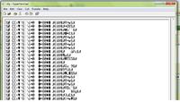
Think the problem lies that I still cant get PIR1.CCP1IF to clear ( despite clearing in the code ). I just debugged the code and relised that once PIR1.CCP1IF is set to 1 , it doesnt clear. Quite weird. The output on the hyperterminal is shown in the attached image.


Input :

Pin: RC2 (CCP1)
Input Signal on RC2 : 20 Khz , 5 V , 50% duty cycle [from function generator]
uC = PIC18F4620 on PICDEM 2 demo board

- - - Updated - - -

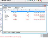
Sample t1, t2, Gap.


Interesting, I presumed by referring to the output as garbage, you meant the numerical values made no sense.

However, in this case the numerical to ASCII string conversion does not appear to be functioning as expected.

I appreciate the info, I'll work on it at this end.

BigDog
 

The issue with the numerical to string conversion is entirely separate from the capture timer issue.

Although not the correct value, Gap does contain a reasonable positive value after the capture operation.


If you manually set the variable Gap to a numerical value and then have the ultoa() routine perform the conversion what is the resulting string?

Can you successfully output a string stored in the character array str?


BigDog
 

If you manually set the variable Gap to a numerical value and then have the ultoa() routine perform the conversion what is the resulting string?

Can you successfully output a string stored in the character array str?


BigDog

Hmm looks like I cant. I manually set Gap to 10 and getting following on screen

E†
E†
E†
E†
E†
E†
E†
E†
E†

- - - Updated - - -

Works with itoa(Gap, str) though. Im getting 10 on screen finally.
 

I often prefer to use the sprintf() routine when constructing debugging or diagnostic messages. The sprintf() may utilize more storage, however that shouldn't be an issue in this case.


Concerning the test signal from the function generator, have you ensured the signal is properly DC biased so the minimum signal level is 0V (GND).

You certainly don't want to apply a -5V level to any of the PICs pins.


BigDog
 

Status
Not open for further replies.

Similar threads

Part and Inventory Search

Welcome to EDABoard.com

Sponsor

Back
Top